Transcription of REX-C100 INSTRUCTION
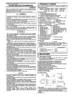
1 INSTRUCTION . REX-C100 SERIES manual . Notes: Make sure that this INSTRUCTION manual is always readily available to personnel who use the REX-C100 series. The contents of the INSTRUCTION manual are subject to change without notice. If you have any questions regarding the manual , contact one of our sales people, our nearest sales office, or the place where you have purchased the controller. 1. PRODUCT CHECK. Check whether the delivered product is as specified by referring to the following model code list. O Model code C100 QQQ - Q~ QQ.. Control action Second alarm [ALM2]. F : PID action [Reverse action] N : No second alarm D : PID action [ Direct action] A : Deviation high alarm *2. B : Deviation low alarm *2. Input type C : Deviation high / low alarm *2. See input range table Model code page 9 D : Band alarm E : Deviation high alarm *3.
2 Input range F : Deviation low alarm *3. See input range table Model code page 9 G : Deviation high / low alarm *3. H : Process high alarm *2. Control output [OUT] J : Process low alarm *2. M : Relay contact K : Process high alarm *3. V : Voltage pulse L : Process low alarm *3. 8 : Current 4 to 20mA DC P : Heater break alarm (CTL-6). G : Trigger (for triac driving) *1 S : Heater break alarm (CTL-12). R : Control loop break alarm *4. First alarm [ALM1]. N : No first alarm *1 When control output is trigger output A : Deviation high alarm *2 for triac driving, only the first alarm is B : Deviation low alarm *2 available. C : Deviation high / low alarm *2 *2 Without hold action. D : Band alarm *3 With hold action E : Deviation high alarm *3 *4 As control loop break alarm, only either F : Deviation low alarm *3 the first alarm or second alarm is G : Deviation high / low alarm *3 selected.
3 H : Process high alarm *2. J : Process low alarm *2 C Confirm that power supply voltage is also K : Process high alarm *3 the same as that specified when ordering. L : Process low alarm *3. R : Control loop break alarm *4 Accessories C Mounting brackets (2 pcs.). C INSTRUCTION manual (1 copy). -1- 2. MOUNTING. Dimensions Unit : mm (inch). * Dimensions in inches are shown for reference Mounting procedures Thickness of panel board: 1 to 5mm or 5 to 9mm ( to inch or to inch). u When the controllers are mounted on panel with 1 to 5mm in thickness Make a rectangular cutout corresponding to the number of controllers to be mounted on panel by referring to the panel cutout dimensions. Since the mounting brackets are already installed on the controller, insert the controller into the panel from the panel front without removal of the brackets (Fig.)
4 1). u When the controllers are mounted on panel with 5 to 9m in thickness Remove the mounting brackets from the controller with a slotted screwdriver. Engage each mounting bracket with holes marked with " on the housing (Fig. 2) and then insert the controller into the panel from the panel front. Fig. 1. O Cautions for mounting Mo unting bracket Avoid the following location where the controller is mounted. C Location where ambient temperature is more than 50EC. (122EF) or less than 0EC (32EF). C Location where humidity is high. C Location where corrosive gas is generated. C Location where strong vibration and shock exist. C Location where flooding and oil splash exist. C Location where much dust exists. C Location where inductive disturbance is large and other location where bad influence is exerted on electric instrument.
5 Fig. 2. -2- 3. WIRING. Rear terminals Notes 1. Terminals which are not used according to the controller type are all removed. 2. For thermocouple input, no metal piece is attached to terminal No. 10. Instead, the temperature compensation element in the internal assembly is projected through a hole at terminal No. 10. Do not damage the above temperature compensation element when the internal assembly is removed from the case. O Cautions for wiring (1) Conduct input signal wiring away from instrument, electric (3) For wiring, use wires conforming to domestic equipment power and load lines as such as possible to avoid standard of each country. noise induction. (4) About 5 to 6 sec. are required as the (2) Conduct instrument power wiring so as not to be influenced preparation time of contact output during by noise from the electric equipment power.
6 Power ON. Use a delay relay when the output If it is assumed that a noise generation source is located near line, is used for an external interlock circuit. the controller and the controller is influenced by noise, use a noise filter (select the filter by checking instrument power (5) The figures below show the REX-C100 circuit supply voltage.) configuration. When connecting wires, note that the power, input, MCU and output circuits C Sufficient effect may not be obtained depending on the are isolated independently, while the inside of filter. Therefore, select the filter by referring to its the input and outputcircuits are not isolated. frequency characteristic, etc. For instrument power wiring, if it is assumed that noise exerts a bad influence upon the controller, shorten the distance between twisted power supply wire pitches.
7 (The shorter the distance between the pitches, the more effective for noise reduction). Install the noise filter on the panel which is always grounded and minimize the wiring distance between the noise filter output side and the controller power terminals. Otherwise, the longer the distance between output side and instrument power terminals, the less effective for REX-C100 circuit configuration noise. Do not install fuses and / or switches on the filter output signal since this may lessen filter effect. -3- WIRING AND NAME OF PARTS. Wiring example ~2N-HA. GG-M*-~. REX-C100 FGG. 1. NAME OF PARTS. Set-value increment key C Used when the number needs to be increased for set-value change. Measured-value (PV) display unit [Green]. C Displays measured-value (PV). C Displays a parameter symbol in the parameter setting mode. Set-value (SV) display unit [Orange].
8 C Displays set-value (SV). C Displays set-value corresponding to the parameter symbol displayed on the measured- value (PV) display unit. Set (SET) key C The set-value thus changed is entered Control output (OUT) lamp [Green]. C Parameters in the parameter setting mode are C Lights up when the control output is turned ON. selected in due order. C Can select PV / SV display mode, SV setting Auto-tuning (AT) lamp [Green]. mode, and parameter setting modes. C Flashes during auto-tuning. Setting digit shift key First alarm (ALM1) lamp [Red]. C Used when the cursor (brightly lit) is moved to C Lights up when the first alarm is turned ON. the digit whose number needs to be changed for C When a control loop break alarm (LBA) is set-value change. selected as the first alarm, this lamp lights up. Set-value decrement key Second alarm (ALM2) lamp [Red].
9 C Used when the number needs to be decreased C Lights up when second alarm is turned ON. for set-value change. C When either a heater break alarm (HBA) or control loop break alarm (LBA) is selected as the second alarm, this lamp lights up. -4- 5. OPERATION. Calling-up procedure of each mode PV / SV display mode : Press the key. : Press the key for more than 5 sec C Displays measured-value (PV) on the measured-value (PV) display unit and set-value (SV) on the set-value (SV). display unit. Usually the control is set to this mode excepting that the set-value (SV) and/or the parameter set- value are changed. PV / SV display mode C Pressing the key lights the least significant digit on the set-value (SV) display unit brightly. C Pressing the , and keys can change the set- value (SV). In order to register the value whose setting was changed, always press the key after the value is changed.
10 < Initial value prior to shipment >. * Set-value (SV) 0EC (EF) or (EF). Input type code / input range display * Desired value for control. This controller, with the power turned ON, displays C When key operation is not performed for more than 1. automatically the input type code on the measured-value (PV) minute, the controller returns to the PV / SV display display unit and the input range, on the set-value (SV) display mode. unit, respectively. Example : For a controller with the K thermocouple input Parameter setting mode type and input range from 0 to 1372EC. Displays the input type code. C If the key is pressed in succession for more than 5. : Indicates input abbreviation. sec. in the PV / SV display or SV setting mode, the : Indicates engineering controller is set to the parameter setting mode. unit. ( : EF). : Indicates input type.