Transcription of REX - C100 REX - C700 REX - C400 REX - C900 REX - C410 ...
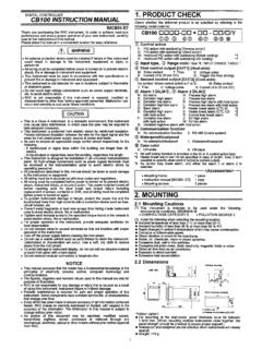
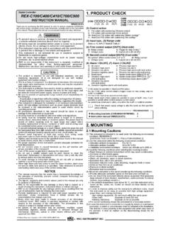
1 REX - C100 REX - C700 REX - c400 REX - c900 REX - c410 initial SETTING MANUALRKC RKC INSTRUMENT FRANKLIN PTY LTDPH. (07) 3391 4865 This is a manual for the initial setting of the REX-C100, - c400 , - c410 , -C700, & - c900 . Do nottouch or adjust parts other than those covered in this manual . The instrument was manufacturedand delivered under close quality control by us. However, is some subject troubled or noted, yourkindly announce and advice to our business department, nearest business office also agent whereyou bought is very much O N T E N T set mode the initial set mode .. the initial set mode .. of each parameter .. parameter setting .. 4(1)Input type selection .. 5(2)Engineering unit and cooling type selection .. 6(3)Selection of break alarm (HBA, LBA) etc.
2 7(4)First alarm (ALM1) type selection .. 8(5)Second alarm (ALM2) type selection .. 9(6)Control output selection etc..11(7)Energize/de-energize alarm selection etc.. 12(8)PV bias setting .. 13(9)Differential gap setting of ON/OFF action .. 13(10)Differential gap setting of first alarm (ALM1) .. 13(11)Differential gap setting of second alarm (ALM2) .. 13(12)High-limit setting for set-value (SV) .. 14(13)Low-limit setting for set-value (SV) .. parameter checks .. n i t i a l s e t m o d e c h a n g i n Entering the initial set mode(1)Press the key to display the set data locking parametersymbol on the measured-value (PV) display this time, the least significant digit on the set-value (SV)display unit lights brightly. The digit which lights brightly issettable.
3 (2)Press the key to shift the digit which lights brightly up tothe hundreds digit. The digit which lights brightly shifts asfollows every time the key is pressed.(3)Press the key to set . Pressing the key incrementsnumerals, and pressing the key decrements numerals.:No initial set mode locked(4)Hold both the (A) and (B) keys simultaneouslyuntil order to enter the initial set mode, always set the data locking to . Any setting other than cannot enter the initial set the controller is set to the initial set mode, all outputs are turned example of the REX- c900 is described here, but the same procedure applies to othercontrollers (REX-C100, - c400 , - c410 , and -C700). the initial set mode(1)Exits from the initial set modeKeep pressing both the key (A) and (B) keys simultaneously for more than 5 seconds can enter thePV/SV display mode.
4 Even if the controller exits from the initial set mode at any point, the setting mode so far set becomes valid.(2)Locks the initial set mode (Change the content of set data lock setting) the key to enter the parameter setting the key by required number of times to show on the measured-value (PV) the key and keys to set . Press the key to register .CautionIf the controller exits from the initial set mode, confirm that set data lock setting is set to .< Each status when power failure occurs in the initial set mode > Setting prior to power failure is valid Instantaneous power failure (within 20 msec.) does not exert bad influence on the instrument. If long power failure occurs, the instrument exits from its initial set mode. After power recovery, the instrumentis set to the PV/SV display mode.
5 The measured-value (PV) at this time shows that at the time of powerrecovery, and the set-value (SV) is the same as that before power e t t i n of each parameter appears on the display, and every press of the key advances the parameter symbol as shown inthe following table. After one cycle, the display shows .MEASURED-VALUE (PV)DISPLAY UNITSETTING DESCRIPTIONI nput type selectionEngineering unit selection (EC, EF)Heater break alarm (HBA) selectionControl loop break alarm (LBA) selectionSpecial specification [Z-132] selectionSelection of control loop break alarm output terminalsFirst alarm (ALM1) type selectionFirst alarm (ALM1) hold action selectionSecond alarm (ALM2) type selectionSecond alarm (ALM2) hold action selectionDirect / reverse action selectionControl action type selectionControl output type selection (Heating / cooling side)Energize / de-energize alarm selectionSpecial specification [Z-124] selection cannot be bias settingDifferential gap setting of ON / OFF actionDifferential gap setting of first alarm (ALM1) No display appears when no first alarm (ALM1)
6 Function is gap setting of second alarm (ALM2) No display appears when no second alarm (ALM2) function is setting for set-value (SV)Low-limit setting for set-value (SV) parameter settinguMethod of setting(2)Press the key to display the input type selection parametersymbol ( ) on the measured-value (PV) display this time, the least significant digit on the set-value (SV)display unit lights brightly. The digit which lights brightly issettable.(3)Press the key to shift the digit which lights brightly up tothe tens digit. The digit which lights brightly shifts as followsevery time the key is pressed.(4)Press the key to set . Pressing the key incrementsnumerals, and pressing the key decrements numerals.:Thermocouple type L(5)After finishing the setting, press the key toregister (shifts to next parameter).
7 No key operation is performed for more than 60 sec. during setting or when anyparameter other than is displayed, the display returns to . example of the REX- c900 is described here, but the same procedure applies to other controllers(REX-C100, - c400 , - c410 , and -C700).-5-(1)Input type selection ( )Set-value (SV) display unitVALUEINPUT TYPEHARDWAREKJLENaTCRSBW5Re / W26 RePLIITUbPt100 S (JIS / IEC)RTDJ Pt100 S (JIS)c0 to 5 V DCVoltage1 to 5 V DCd0 to 20 mA DCCurrent4 to 20 mA setting so as to meet the instrument specification (input type).Setting change between different symbols may cause malfunction, but the setting can be changed whenhardware types have the same symbol. However, when the setting is changed, always reset and . (See page 14).2. setting displays are only and.
8 -6-(2)Engineering unit and cooling type selection ( )Set-value (SV) display unitVALUEDESCRIPTIONECE ngineering unitEFselectionAir-cooling (Type A) 1 Cooling typeWater-cooling (Type W) 2selectionFixed 1 Type A : Heating / cooling PID action (Air-cooling) 2 Type W : Heating / cooling PID action (Water-cooling) the voltage and current input types, the engineering unit setting of EC or EF is control action is of the type D (PID action [direct action] or type F (PID action [reverse action] ), Coolingtype selection setting is not set the upper 2 digits to numeric values other than since they are not setting displays are only and .-7-(3)Selection of break alarm (HBA, LBA) etc. ( )Set-value (SV) display unitVALUEDESCRIPTIONW ithout HBA functionHeater break alarm (HBA)With HBA functionselectionWithout LBA functionControl loop break alarm With LBA function(LBA) selectionWithout Z-132 specificationSpecial specificationWith Z-132 specification [Z-132] selectionFirst alarm sideSelection of control loop Second alarm sidebreak alarm output terminals Z-132 specification : Heater break alarm output is With HBA function setting is ignored for the following instruments :CInstrument with deviation or process alarm as the second alarm (ALM2)CInstrument with control loop break alarm (LBA)CInstrument whose control output is the current output type2.)
9 With LBA function setting is ignored for the following instruments :CInstrument with deviation or process alarm as the first alarm (ALM1) and second alarm (ALM2)CInstrument with heater break alarm (HBA)CInstrument whose control action is type W (Heating / cooling PID action [Water-cooling] ) or type A(Heating / cooling PID action [Air-cooling] ). the instrument without heater break alarm (HBA), With Z-132 specification setting is setting displays are only and .-8-(4)First-alarm (ALM1) type selection ( )Set-value (SV) display unitVALUEDESCRIPTIONNo first alarmHigh alarmLow alarmDeviationFirst alarm (ALM1)High / Low alarmalarmtype selectionBand alarm(See page 10)High alarmProcessLow alarmalarmWithout alarm hold actionFirst alarm (ALM1)With alarm hold actionhold action following instrument is set to.
10 CInstrument without the first alarm (ALM1).CInstrument which outputs control loop break alarm (LBA) from the first alarm side. [setting details : For ]2. setting displays are only and .-9-(5)Second-alarm (ALM2) type selection ( )Set-value (SV) display unitVALUEDESCRIPTIONNo second alarmHigh alarmLow alarmDeviationSecond alarm (ALM2)High / Low alarmalarmtype selectionBand alarm(See page 10)High alarmProcessLow alarmalarmWithout alarm hold actionSecond alarm (ALM2)With alarm hold actionhold action selectionCInstrument without the second alarm (ALM2).CInstrument with the heater break alarm (HBA). following instrument is set to .CInstrument without the second alarm (ALM2).CInstrument with the heater break alarm (HBA).CInstrument which outputs control loop break alarm (LBA) from the second alarm side.