Transcription of RF Capacitance Level Controls - SOR Inc.
1 SEE MORE AT Request Quote RF Capacitance Level Controls CAC-8A-00-6 681R7. Reliability 316SS, Telflon or Kynar probes Features and Benefits Low maintenance costs Can be used in virtually every type of chamber No moving parts Set point/span are completely adjustable Interface measurement with on/off Withstands temperatures up to and continuous output 400oF (204oC). Unaffected by changes in pressure, Withstands pressure up to 2000 psig temperature, specific gravity, vapor (138 bar). or density Agency Listings/Certification Versatile - can be used with both Select models with CSA, FM, IECEx, conductive and non-conductive INMETRO, Rostechnadzor (RTN). substances. Manages a variety of liquids, granular solids, powders Meets most code and customer and slurries. requirements. Dielectric range is unlimited Form 1100 ( ) SOR Inc. | 913-888-2630 | Registered Quality System to ISO 9001 1/25.
2 RF Capacitance Level Controls Principle Operating Principle Non-Conductive Substances RF Capacitance Level Controls are based on an The structure of the capacitor actually changes in electronic device called a capacitor. The capacitor a Level application. One plate is the probe and the is a device that stores energy. This energy is not other is the wall of the tank (see following figure). stored in the probe; rather, the RF Capacitance These do not change, nor does the distance Level control is merely measuring how much energy between them. The only thing that changes is the can be stored. The amount of Capacitance the RF dielectric constant. Air has a dielectric constant of Capacitance Level control is measuring is extremely one; anything else you measure will have dielectric small and is measured in picofarads (1 X 10-12) value greater than one. farads. The capacitor is made up of two conductive plates Bare Metal Probe parallel to each other.
3 Separating the two plates is an insulator. Metal Hydrocarbon Tank Wall When the substance Level increases, the dialectic of the substance is replacing the air Conductive Conductive and causes the Capacitance to increase. The Plate Plate preset Capacitance value is equal to the set point Insulating Medium Level wanted and trips a switch when the Level is The amount of energy a capacitor can store is reached. The transmitter creates a linear output in influenced by several things. First, a larger plate relationship to the Capacitance measured. area results in more space to store energy. Second, more space between the plates reduces Conductive Substances the amount of energy storage. Finally, a higher The substance between the two plates has to be dielectric constant media can contain more energy an insulator in order to have a capacitor. When than a lower dielectric media. The dielectric is a conductive material is between the plates, an where the actual Capacitance is developed.
4 The electrical short is created. This, in turn, signals the following chart shows the dielectric constant Level transmitter to indicate a high Level . A Teflon and conductivity for some sample materials. insulator around the sensor will prevent this from happening, as the figure below demonstrates. Insulated Probe Water Substances are considered either conductive or An electrical connection is created through the non-conductive. Non-conductive materials have a conductive substance from the tank wall and the dielectric less than 10 or a conductivity less than Teflon probe. When the Level in the tank rises, 10 siemens/cm. Conductive materials have a the capacitor is created by the metal probe rod, dielectric constant greater than 10 or a conductivity the substance being measured and the probe greater than 10 siemens/cm. Interestingly, there insulator (Teflon), where the sensor rod and is a similar relationship between dielectric constant substance are the plates and insulator is the and conductivity.
5 Non-conductive substances tend dielectric. This means that rather than measuring to have low dielectric constants and conductive the dielectric of the substance, the dielectric of substances tend to have high dielectric constants. the probe where it is covered by the substance is being measured. 2/25 Registered Quality System to ISO 9001 | 913-888-2630 | Form 1100 ( ) SOR Inc. RF Capacitance Level Controls Principle When there is a conductive coating on the probe, Restrictions of RF a non-RF unit will indicate the Level at the top of Sensitive to changes in material dielectric the coating. By looking at the conductivity, an (Note: dielectric compensation additives help, RF system can reduce the error caused by the but the liquid can stratify.) coating (see following figure). Consider this: At the Normally needs field calibration, which requires actual Level , the amount of capacitive reactance a change in Level (impedance) is low because the space between Dependent on contact with the substance the tank wall and probe is filled with a conductive being measured liquid.
6 However, at the coating on the probe, there Conductive coatings can build up on the is also a large air space between the probe and sensor and create false readings tank wall. This air space results in a high amount of capacitive reactance. The Difference Between RF Capacitance and RF Admittance RF Unit Contrary to popular belief, there really isn't an application difference between RF Capacitance and RF Admittance. The only difference is in the electronics; the overall performance of the unit remains the same. That's where the RF part Coating comes in, as the following will explain: High Xc RF measurement is actually measuring Low Xc Capacitance , as well as Capacitance reactance Level (impedance). The energy (Radio Frequency) is traveling from one conductive plate to the other. The following equation represents Capacitance reactance: Xc = 1. 2 fc where Xc = Capacitance Reactance (Ohms).
7 2 = Radians in a 360o cycle of AC (alternating current). f = Frequency of AC (hertz). C = Capacitance of system (in farads). Form 1100 ( ) SOR Inc. | 913-888-2630 | Registered Quality System to ISO 9001 3/25. RF Capacitance Level Controls Principle The Difference Between RF Capacitance and RF Admittance Look at the formula for capacitive reactance. Since The Level is represented on the vertical axis in we are striving to measure the Capacitance , C these two graphs. Changes in the resistance cannot change, and 2 is a constant and cannot are represented on the horizontal axis. A vector change. The only thing left we can change is the representing a combination of the two (impedance). frequency. If the frequency is increased (RF), the is shown to the left. The inverse of this graph is capacitive reactance decreases. shown below. As you can see, an admittance measurement is just the inverse of a Capacitance measurement.
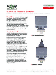
8 Capacitive The important part, as previously stated, is the RF.. Reactance Impedance Capacitive Susceptance Admittance Resistance Conductance Use this chart to select the RF instrument that best meets your needs. Designator Line Power Loop Power Single-Point Sensing 651 651. Integral Mount Electronics Pages 5-6 Pages 5-6. Integral Mount Electronics with 681 681. Sensor Monitor (Self-Test) Pages 7-8 Pages 7-8. Remote Mount Electronics with 681 681. Sensor Monitor (Self-Test) Pages 7-8 Pages 7-8. Multiple-Point Sensing 660. Alarm or Pump control N/A. Pages 9-10. 4/25 Registered Quality System to ISO 9001 | 913-888-2630 | Form 1100 ( ) SOR Inc. RF Capacitance RF Switches Level Controls Single Point 651 Single-Point RF Switch The 651 provides basic, single-point switching for use as an alarm or indicator. It's virtually immune to process coatings on the probe, making it a useful solution for many tough Level applications.
9 This immunity, combined with the absence of any moving parts, makes the 651. well suited for applications that are difficult for other technologies. Features Economical point sensing Suitable for 12 VDC service . FM Approved, CSA Certified hazardous locations, IEC Certified . Field-selectable failsafe Product Specifications Input Power - Line 120 VAC, 50/60 Hz Response Time seconds 240 VAC, 50/60 Hz 24 VDC Enclosure NEMA 4X; IP65. 12 VDC Environmental Rating Input Power - Loop 12-28 VDC Electrostatic 8000 volts (Line). Discharge Protection 4000 volts (Loop) Output Type - Line 10A DPDT, 250 VAC 10A DPDT, 30 VDC Line Surge Suppression 1000 volts line DC rating shown for voltage EMC. resistive loads 5A DPDT for 12 VDC input power Conduit Connection 3/4 NPT. Output Type - Loop 8 mA (alarm), 16 mA (normal) Ambient -40 to 160oF (-40 to 71oC). Temperature Range Loop Resistive 780 ohms maximum @ 24 VDC.
10 Process Probe Dependent Adjustment Range 0 to 1000 pF Temperature Range Sensitivity pF. Maximum Probe Dependent Repeatability Process Pressure Failsafe Field-selectable Weight lbs. ( kg). Maximum Current 12 VDC - 100 mA. Draw (line power) 24 VDC - 50 mA. 120 VAC - 20 mA. 240 VAC - 10 mA Form 1100 ( ) SOR Inc. | 913-888-2630 | Registered Quality System to ISO 9001 5/25. RF Capacitance Level Controls How to Order The 651 consists of two parts. The first is the electronics and housing. The second is the probe. For probe types and model numbers, see pages 21-25. Model Number System 651 K 7-TTYY. 651 RF Admittance Switch with 120. VAC power supply, oversized nameplate 2 Accessories & Certificates and epoxy-coated housing. Al CSA Intrinsically Safe*. Power Supply 1 CS Fl CSA Explosion Proof Listing*. FM Intrinsically Safe*. FM FM Explosion Proof Listing*. 12 VDC 5. MB IEC Certified Intrinsically Safe*.