Transcription of Ultrasonic Point Level Switches - Pressure, Level, …
1 | 913-888-2630 | Registered Quality System to ISO 90011/24 Form 1145 ( ) SOR Inc. Cost In addition to the price of the instrument, you must consider the cost of installation, set-up and You need to factor in the frequency of preventative maintenance. Also, consider the cost of keeping key spare parts on the What skill Level is required of your maintenance personnel to service the Point Level Switches are a cost-effective solution for your applications. Installation requires mounting the sensor (threaded or flanged) to the vessel, connecting the power and control wires, and applying power. There is no additional set-up or calibration required. Since it is an electronic instrument with no moving parts, preventive maintenance is limited to an annual visual inspection.
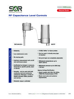
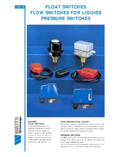
2 The only recommended spare part is the board at a quantity of one board for every 10 units. A technician with basic electrical skills (wiring) can service the use an Ultrasonic switch over other Level technologies? Depending upon your application, there may be three or four technologies equally suited for your application; however; only one will be the best choice when considering its features and Single Point722 Dual Point711 Single PointUltrasonic Point Level SwitchesFeatures & BenefitsSEE MORE AT Request QuoteRegistered Quality System to ISO 9001 | 913-888-2630 | 1145 ( ) SOR Inc. ApplicationsUltrasonic SwitchesUltrasonic Switches are simple to apply and use. There are only a few limitations to their use: The media must be liquid Process temperature between -40 and 250oF (-40 to 121oC) The media must have less than 5% suspended solids No aeration in fluids with a viscosity of 100cP (30W motor oil) or greaterThe following chart will assist you in selecting the right product for your Ultrasonic switch is a device that uses inaudible high-frequency sound (ultrasound) to detect the presence or absence of a liquid at a designated Point .
3 The device consists of an electronic control unit and a Level Switches use the properties of sound transmission in vapor and liquids to detect liquid Level . When sound travels in air, it loses a great deal of signal strength. When traveling in liquid, sound retains almost all of its signal detect liquid Level , we must determine if there is a liquid or gas (air) in the gap. Since liquids have a higher density than gasses, it is easier to transmit sound through them. One side of the sensor gap transmits sound, the other side detects it. When liquid is present, a high amount of sound is received at the detection side. When gas (air) is present, a small amount of sound is received. The electronics detect this difference and switch a relay SensingLine PowerLoop PowerIntegral Mount Electronics701 Pages 4-5711 Pages 6-7701 Pages 4-5 Integral Mount Electronics with Sensor Monitor (Self-Test)721 Pages 8-9721 Pages 8-9 Remote Mount Electronics701 Pages 4-5711 Pages 6-7701 Pages 4-5 Remote Mount Electronics with Sensor Monitor (Self-Test)721 Pages 8-9721 Pages 8-9 Dual- Point SensingLine PowerLoop PowerAlarm or Pump Control712 Pages 10-11N /AAlarm or Pump Control with Sensor Monitor (Self-Test)722 Pages 12-13N | 913-888-2630 | Registered Quality System to ISO 90013/24 Form 1145 ( ) SOR Inc.
4 PrincipleUltrasonic SwitchesApplication ConditionsUltrasonic Level Switches can be used in a wide variety of applications without any calibration or setup. However, there are limitations to the types of process they will work in. The factors below must be taken into consideration before selecting an Ultrasonic Level switch for your application. Liquids only - the process media must be a liquid. The Ultrasonic Level switch cannot detect the difference between two gases or a gas and a solid. The even density of a liquid is required for proper detection. Clean liquids only - a liquid that has too high a percentage of solids will not transmit sound well enough to allow detection. Typically 5% suspended solids are the maximum amount allowed.
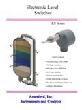
5 The liquid must flow - an application where the liquid cannot drain out of the sensor gap will cause false alarms. If a liquid is too viscous to flow out of a 3/4 gap then the unit will not operate properly. Sometimes this can be solved by different mounting, but some liquids are just too viscous. No (or few) bubbles - especially in fluids with a viscosity higher than 100cP (30W motor oil). Large bubbles in thick fluids will block the sound signal from crossing the gap. Low viscosity fluids can have a fairly large amounts of bubbles as they tend to be very small (Alka-Seltzer in water).If these guidelines are properly observed, the Ultrasonic Level Switches will provide trouble-free operation without any calibration or periodic switch sensors contain two piezoelectric crystals, one transmits sound and one receives sound.
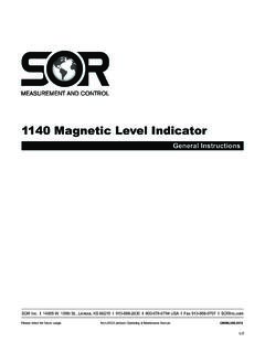
6 Each crystal is mounted on one side of a gap in the metal sensor. The transmit crystal generates high frequency sound (1 MHz to 3 MHz) that is directed across the gap to the receiver crystal. The receiver crystal converts the sound energy received into an electric signal, which is processed by the electronics to determine if the gap has liquid or air in drawing below shows the basic construction of an Ultrasonic Level switch sensor. An electrical signal is sent to the transmit crystal, which causes it to vibrate and produce high frequency sound. The receive crystal converts the high frequency sound that strikes it to another electrical signal, which is sent back to the electronics for processing. The sound energy that makes it across the sensor gap is very weak in air, and becomes very strong in Quality System to ISO 9001 | 913-888-2630 | 1145 ( ) SOR Inc.
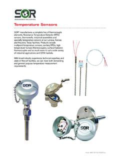
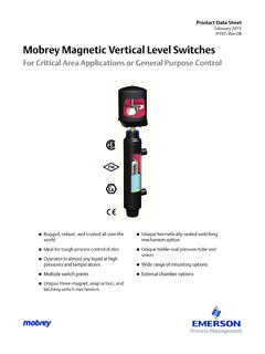
7 701 Single Point Ultrasonic SwitchesThe 701 tip-sensitive Ultrasonic switch is a single- Point device designed for economical detection of clean liquids. There are no moving parts and no calibration. The 701 is available either integral or remote mounted. An optional time delay can be used to eliminate false alarms due to turbulence in the process. An optional field selectable fail-safe switch is also available. The standard unit is set to High- Level Failsafe (HLFS)Features No calibration required 10A DPDT relay output FM Approved or CSA Certified for hazardous locations Line and loop powered versions Rostechnadzor (RTN) standard certificate (available upon request)Input Power Line 120 VAC, 50/60 Hz 240 VAC, 50/60 Hz 24 VDC Loop 11-36 VDC Intrinsically SafeFuses Field replaceable (line power only)Output Type Line 10A DPDT, 250 VAC 10A DPDT, 30 VDC DC rating shown for resistive loads Loop 8mA (dry), 16 mA (Wet)-StandardLoop Resistance 765 ohms maximum @ 24 VDCR epeatability (2mm)Failsafe HLFS-Standard.
8 Field selectable is optionalProduct Specifications Maximum Current Draw (Line Power) 24 VDC 100 mA 120 VAC 35 mA 240 VAC 18 mAResponse Time On 0 second Off 1 secondEnclosure Environmental Rating NEMA 4X; IP65 Conduit Connection 3/4 NPTM aximum Remote Distance 50 feet ( meters)from SensorAmbient Temperature Range -40 to 160oF (-40 to 71oC)Process Temperature Range -40 to 250oF (-40 to 121oC)Maximum Process pressure 2000 psig (138 bar)Weight* lbs. ( kg)701 Single Point * See page 23 for sensor | 913-888-2630 | Registered Quality System to ISO 90015/24 Form 1145 ( ) SOR Inc. Ultrasonic SwitchesHow to OrderPower Supply24 VDC (K1 and R1 housings only)120 VAC (K1 and R1 housings only) 240 VAC (K1 and R1 housings only) 24 VDC (Loop) (K4 and R4 housings only)Electrical Housing Integral K1 Remote R1 Integral (9 Power Only) K4 Remote (9 Power Only) R (order remote cable part number 300-XX-S, XX = length in feet - max 50 feet)701 K1 U P7 C FS Model NumberAccessoriesAl CSA Certified Intrinsically Safe* (9 power only) (K4 housings only)
9 BK Remote electronics flat surface mounting bracket (R housings only) (see pages 14 & 15)CS CSA Certified Explosion Proof*CV Canadian Registration Number (CRN) Process ratings may be affected. Consult the factory for detailsFl FM Approved Intrinsically Safe* (9 power only) (K4 housings only)FM FM Approved Explosion Proof*FS Field selectable Failsafe switch (6, 7, 8 power only)OD On delay time (6, 7, 8 power only) (specify time from chart on page 16)OF Off delay timer (6, 7, 8 power only) (specify time from chart on page 16)PK Pipe mounting kit, BK accessory required (R housing only) (see page 17)PP Fiber tag with customer specified tag informationPY Powder coat epoxy coating applied to housing exteriorRG Gold-contact relay (6, 7, 8 power only)
10 RR SS nameplate wired to the unit with customer specified tag informationTT SS nameplate permanently affixed to housing with customer specified tag informationVV Fungicidal varnish applied to housing exteriorYY Epoxy coating applied to housing exterior (200 hours - salt spray)701-K1-U-P7-C-FSModel Number SystemThe 701 is comprised of two parts. The first is the electronics and housing; the second is the sensor. Select the electronics and housings on this page and refer to page 18 for the sensor model number. The housing dimensions can be seen on pages 14 & 15. When ordering a remote housing, order remote cable part number 300-XX-S (XX = length in feet). Orders must have complete model numbers, each component must have a designator.