Transcription of RM Core - MMG Canada Ltd.
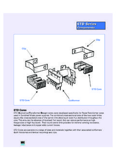
1 RM CoreComponentsRM CoreComponentsRM CoresRM (Rectangular modulus) cores arose due to the demand for coil formers with integrated pins that allow forefficient winding and high PCB packing densities. Clamps engaging in recesses in the core base hold the cores inplace, meaning glue is not normally required in this the cores adhere to specifications laid down in IEC 431 and in DIN 41980. The coil formers adhere to cores are designed for two main applications:-Highly stable, extremely low loss filter inductors and other resonance determining inductors (F58, P11).-Low distortion broadband transmission at low signal modulation (F39, F10, F9).RM cores can also be supplied without the centre hole.
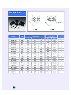
2 These have a higher AL value and cross sectional areaand are used for power transformer applications (F47, F44, F45, F5A).RM CoreCoilformerRM CoreClipClipAdjusterRM 429-900-RM 429-900-Part Number64-020-6664-021-6676-024-95 Parameter l /AEffective LengthEffective AreaMinimum AreaEffective Core Parameters Electrical SpecificationIn accordance with IEC Document 60205. Bobbins/Coil Formers AdjustersMaterialAL ValueToleranceGap LengthEff. PermeabilityPart NumberF9 1700 +30/-20% - 2570 29-900-36F44 800 +30/-20% - 1210 29-900-44P11 900 +30/-20% - 1360 29-900-41P11 63 3% 95 29-901-41*P11 100 3%
3 150 29-902-41*P11 160 3% 240 29-903-41*P11 250 3% 375 29-904-41*P11 100 3% 150 29-912-41**P11 160 3% 240 29-913-41**P11 250 3% 375 29-914-41**MountingNo.
4 Of SectionsPinsPart NumberVertical (AS)1460-901S64 Vertical (AS)1660-903S64 Other pin lengths or variation may be listed at the end of this sectionAL Value63/100160/250 Clip*Part number refers to a pair of cores fitted with a nut for adjust-able inductance assemblies.**Part number denotes a gapped pair without part numbers refer to half cores. Core Dimensions (mm) 4 SOLID29-920-RM 4 SOLID29-920-76-024-95 Parameter l /AEffective LengthEffective AreaMinimum AreaEffective Core ParametersIn accordance with IEC Document numbers refer to half cores.*Part number refers to a pair of pin lengths and versions may be listed at the end of this section Electrical SpecificationMaterialAL ValueToleranceGap LengthEff.
5 PermeabilityPart NumberF9 1900 +30/-20% - 2570 29-920-36F10 2800 +30/-20% - 3790 29-920-37F39 3700 +40/-30% - 5000 29-920-39F44 860 +30/-20% - 1160 29-920-44F44 100 5% 75 29-921-44*F44 160 5% 120 29-922-44*F44 250 5% 188 29-923-44* Bobbins/Coil FormersMountingNo.
6 Of SectionsPinsPart NumberVertical (AS)1460-901S64 Vertical (AS)1660-902S64 ClipPart Number Core Dimensions (mm) 5-29-700-RM 5-29-700-Parameter l /AEffective LengthEffective AreaMinimum AreaEffective Core Parameters Electrical SpecificationIn accordance with IEC Document 60205. Bobbins/Coil Formers AdjustersMaterialAL ValueToleranceGap LengthEff. PermeabilityPart NumberF10 4800 +30/-20% - 3820 29-700-37F39 6000 +40/-30% - 4775 29-700-39P11 1840 +30/-20% - 1460 29-700-41P11 100 3% 80 29-701-41*P11 160 3%
7 128 29-702-41*P11 250 3% 200 29-703-41*P11 315 3% 250 29-704-41*P11 100 5% 80 29-711-41**P11 160 5% 128 29-712-41**P11 250 5% 200 29-713-41**Other pin lengths or variation may be listed at the end of this sectionAL Value100/160250/315 Clip*Part number refers to a pair of cores fitted with a nut for adjust-able inductance assemblies.
8 **Part number denotes a pair of cores without part numbers refer to half Number64-020-6664-021-6676-024-95 MountingNo. of SectionsPinsPart NumberVertical (AS)1460-701S64 Vertical (AS)1660-702S64 Core Dimensions (mm) 5 SOLID29-720-RM 5 SOLID29-720-76-024-95 MountingNo. of SectionsPinsPart NumberVertical (AS)1460-701S64 Vertical (AS)1660-702S64 Parameter l /AEffective LengthEffective AreaMinimum AreaEffective Core ParametersIn accordance with IEC Document numbers refer to half cores.*Part number refers to a pair of pin lengths and versions may be listed at the end of this section Electrical SpecificationMaterialAL ValueToleranceGap LengthEff.
9 PermeabilityPart NumberF9 3840 +30/-20% - 2840 29-720-36F10 4815 +30/-20% - 3563 29-720-37F39 6700 +40/-30% - 4960 29-720-39F47 1520 +30/-20% - 1125 29-720-47F44 1570 +30/-20% - 1160 29-720-44F44 100 5% 74 29-721-44*F44 160 5% 118 29-722-44*F44 250 5% 185 29-723-44* Bobbins/Coil Formers ClipPart Number Core Dimensions (mm)
10 629-730-RM 629-730-*Part number refers to a pair of cores fitted with a nut for adjustable inductance adjustable cores may also be available on request. Part numbers refer to half l /AEffective LengthEffective AreaMinimum AreaEffective Core Parameters Electrical SpecificationIn accordance with IEC Document 60205. Bobbins/Coil Formers AdjustersMaterialAL ValueToleranceGap LengthEff. PermeabilityPart NumberF58 890 +30/-20% - 615 29-730-58P11 2000 +30/-20% - 1385 29-730-41F58 40 3% - 28 29-7302-58*F58 63 3% 44 29-7303-58*F58 100 3%