Transcription of RNCP Series Stackpole Electronics, Inc.
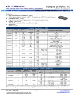
1 Rev Date: 03/09/2020 1 This specification may be changed at any time without prior notice Please confirm technical specifications before you order and/or use. RNCP Series High Power Anti-Sulfur Thin Film Chip Resistor Stackpole Electronics, Inc. Resistive Product Solutions Features: Higher power ratings than standard thick film chips Absolute TCRs to 100 ppm/ C Inner termination engineered to deter sulfur contamination Absolute tolerances to 1% 100% RoHS compliant and lead free without exemption Halogen free REACH compliant (1) Power rating for each package size is valid if ambient temp 80 C and terminal temp 105 C (2) Lesser of PR or maximum working voltage Certain resistance values will require a higher minimum order quantity.
2 Contact Stackpole Customer Service for details. Please refer to the High-Power Resistor Application Note (page 5) for more information on designing and implementing high power resistor types. Electrical Specifications Performance Characteristics Mechanical Specifications WidthBody HeightTop TerminationBottom TerminationLBody LengthRNCP1206 Type / CodeRNCP08051%, 5% - - - 100 KOhmic Range ( ) and ToleranceTCR (ppm/ C)Type / CodeMaximum Working Voltage (V)(2)Maximum Overload Voltage (V) 100400 Power Rating (W)(1) @ 70 C Test ItemReference StandardCondition of TestTest Limits ( R)F: (1% + )J: (2% + ) 100 ppm/ C times rated voltage for 5 Paragraph.
3 Time OverloadTemperature Coefficient of ResistanceMIL-STD-202F Method 304; + 25 ~ +125 C 1000 hours at T = 125 C. Unpowered. Measurement at 24 2 hours after test Temperature Exposure (Storage)MIL-STD-202 Method 108F: (2% + ) J: (2% + ) Rev Date: 03/09/2020 2 This specification may be changed at any time without prior notice Please confirm technical specifications before you order and/or use. RNCP Series High Power Anti-Sulfur Thin Film Chip Resistor Stackpole Electronics, Inc. Resistive Product Solutions Power Derating Curve: Performance Characteristics (cont.)
4 0155 C-600 Ambient Temperature ( C)120140160180100 Power Load (%)10070 C8060402020406080-55 CTest ItemReference StandardCondition of TestTest Limits ( R)F: ( + )J: (1% + )Note: R 10 : F/J: (1% + )1000 hours, T = 24 hours/cycleNotes: Steps 7a & 7b not : NA0402: Kg, 0805: 1 Kg0603: Kg, 1206: KgPressure X kgf a pressure rod for 60 : ( + ) J: (1% + )F: ( + ) J: (1% + )3 mm Flex (Bending)AEC-Q200-006 Terminal Strength (SMD)F: (3% + ) J: (3% + )Operational LifeF: (1% + ) J: (3% + )Condition B: Immerse the specimens in an eutectic solder at 260 5 C for 10 1 >95% area covered with tin1000 hours TA = 125 C at rated power.
5 Measurement at 24 2 hours after test conclusion. Remark: Mounted quantity: Mounted 2 pieces on 1 Method 108245 5 C solder, 2 seconds. dwell Solder: Sn / Ag / Cu to Soldering HeatMIL-STD-202 Method 210F: ( + ) J: (1% + )Moisture ResistanceMIL-STD-202 Method 1061000 hours 85 C / 85% RH. Specified conditions: 10% of operating power. Measurement at 24 2 hours after test HumidityMIL-STD-202 Method 103 Operating temperature range is -55 C to +155 C1000 cycles (-55 C to +125 C).
6 Measurement at 24 2 hours after test CyclingJESD22 Method JA-104F: (1% + ) J: (2% + ) Rev Date: 03/09/2020 3 This specification may be changed at any time without prior notice Please confirm technical specifications before you order and/or use. RNCP Series High Power Anti-Sulfur Thin Film Chip Resistor Stackpole Electronics, Inc. Resistive Product Solutions Packaging Specifications RNCP0402 (2 mm Pitch Paper) RNCP0603, 0805, 1206 (4 mm Pitch Paper) Type / ( )Type / Tape Rev Date: 03/09/2020 4 This specification may be changed at any time without prior notice Please confirm technical specifications before you order and/or use.
7 RNCP Series High Power Anti-Sulfur Thin Film Chip Resistor Stackpole Electronics, Inc. Resistive Product Solutions Reel Specifications Peel-off Force Specifications Peel-off force of paper and blister tape is in accordance with JIS-C5202 , that is, to at a peel-off speed of 300 mm/minute. Type / A B cWSolder Land Pattern Type / Rev Date: 03/09/2020 5 This specification may be changed at any time without prior notice Please confirm technical specifications before you order and/or use. RNCP Series High Power Anti-Sulfur Thin Film Chip Resistor Stackpole Electronics, Inc. Resistive Product Solutions (Solder: / Ag3 / ) High Power Chip Resistors and Thermal Management Stackpole has developed several surface mount resistor Series in addition to our current sense resistors, which have had higher power ratings than standard resistor chips.
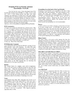
8 This has caused some uncertainty and even confusion by users as to how to reliably use these resistors at the higher power ratings in their designs. The data sheets for the RHC, RMCP, RNCP, CSR, CSRN, CSRF, CSS, and CSSH state that the rated power assumes an ambient temperature of no more than 100 C for the CSS / CSSH Series and 70 C for all other high power resistor Series . In addition, IPC and UL best practices dictate that the combined temperature on any resistor due to power dissipated and ambient air shall be no more than 105 C. At first glance this wouldn t seem too difficult, however the graph below shows typical heat rise for the CSR 100 milliohms at full rated power.
9 The heat rise for the RMCP and RNCP would be similar. The RHC with its unique materials, design, and processes would have less heat rise and therefore would be easier to implement for any given customer. Recommended IR Reflow Profile Peak: 250 +5/-0 C, 5 secondsPre-heat Zone: 150 C to 180 C, 90 30 secondsSoldering Zone: 230 C or higher, 30 10 seconds Rev Date: 03/09/2020 6 This specification may be changed at any time without prior notice Please confirm technical specifications before you order and/or use. RNCP Series High Power Anti-Sulfur Thin Film Chip Resistor Stackpole Electronics, Inc. Resistive Product Solutions The 102 C heat rise shown here would indicate there will be additional thermal reduction techniques needed to keep this part under 105 C total hot spot temperature if this part is to be used at watts of power.
10 However, this same part at the usual power rating for this size would have a heat rise of around 72 C. This additional heat rise may be dealt with using wider conductor traces, larger solder pads and land patterns under the solder mask, heavier copper in the conductors, via through PCB, air movement, and heat sinks, among many other techniques. Because of the variety of methods customers can use to lower the effective heat rise of the circuit, resistor manufacturers simply specify power ratings with the limitations on ambient air temperature and total hot spot temperatures and leave the details of how to best accomplish this to the design engineers.