Transcription of Rock mass classification - Rocscience Inc.
1 1 Rock mass classification introduction During the feasibility and preliminary design stages of a project, when very little detailed information is available on the rock mass and its stress and hydrologic characteristics, the use of a rock mass classification scheme can be of considerable benefit. At its simplest, this may involve using the classification scheme as a check-list to ensure that all relevant information has been considered. At the other end of the spectrum, one or more rock mass classification schemes can be used to build up a picture of the composition and characteristics of a rock mass to provide initial estimates of support requirements, and to provide estimates of the strength and deformation properties of the rock mass. It is important to understand the limitations of rock mass classification schemes (Palmstrom and Broch, 2006) and that their use does not (and cannot) replace some of the more elaborate design procedures.
2 However, the use of these design procedures requires access to relatively detailed information on in situ stresses, rock mass properties and planned excavation sequence, none of which may be available at an early stage in the project. As this information becomes available, the use of the rock mass classification schemes should be updated and used in conjunction with site specific analyses. Engineering rock mass classification Rock mass classification schemes have been developing for over 100 years since Ritter (1879) attempted to formalise an empirical approach to tunnel design, in particular for determining support requirements. While the classification schemes are appropriate for their original application, especially if used within the bounds of the case histories from which they were developed, considerable caution must be exercised in applying rock mass classifications to other rock engineering problems.
3 Summaries of some important classification systems are presented in this chapter, and although every attempt has been made to present all of the pertinent data from the original texts, there are numerous notes and comments which cannot be included. The interested reader should make every effort to read the cited references for a full appreciation of the use, applicability and limitations of each system. Most of the multi-parameter classification schemes (Wickham et al (1972) Bieniawski (1973, 1989) and Barton et al (1974)) were developed from civil engineering case histories in which all of the components of the engineering geological character of the rock mass were included. In underground hard rock mining, however, especially at deep levels, rock mass weathering and the influence of water usually are not significant and may be ignored. Different classification systems place different emphases on the various parameters, and it Rock mass classification 2 is recommended that at least two methods be used at any site during the early stages of a project.
4 Terzaghi's rock mass classification The earliest reference to the use of rock mass classification for the design of tunnel support is in a paper by Terzaghi (1946) in which the rock loads, carried by steel sets, are estimated on the basis of a descriptive classification . While no useful purpose would be served by including details of Terzaghi's classification in this discussion on the design of support, it is interesting to examine the rock mass descriptions included in his original paper, because he draws attention to those characteristics that dominate rock mass behaviour, particularly in situations where gravity constitutes the dominant driving force. The clear and concise definitions and the practical comments included in these descriptions are good examples of the type of engineering geology information, which is most useful for engineering design.
5 Terzaghi's descriptions (quoted directly from his paper) are: x Intact rock contains neither joints nor hair cracks. Hence, if it breaks, it breaks across sound rock. On account of the injury to the rock due to blasting, spalls may drop off the roof several hours or days after blasting. This is known as a spalling condition. Hard, intact rock may also be encountered in the popping condition involving the spontaneous and violent detachment of rock slabs from the sides or roof. x Stratified rock consists of individual strata with little or no resistance against separation along the boundaries between the strata. The strata may or may not be weakened by transverse joints. In such rock the spalling condition is quite common. x Moderately jointed rock contains joints and hair cracks, but the blocks between joints are locally grown together or so intimately interlocked that vertical walls do not require lateral support.
6 In rocks of this type, both spalling and popping conditions may be encountered. x Blocky and seamy rock consists of chemically intact or almost intact rock fragments which are entirely separated from each other and imperfectly interlocked. In such rock, vertical walls may require lateral support. x Crushed but chemically intact rock has the character of crusher run. If most or all of the fragments are as small as fine sand grains and no recementation has taken place, crushed rock below the water table exhibits the properties of a water-bearing sand. x Squeezing rock slowly advances into the tunnel without perceptible volume increase. A prerequisite for squeeze is a high percentage of microscopic and sub-microscopic particles of micaceous minerals or clay minerals with a low swelling capacity. x Swelling rock advances into the tunnel chiefly on account of expansion.
7 The capacity to swell seems to be limited to those rocks that contain clay minerals such as montmorillonite, with a high swelling capacity. Rock mass classification 3 Classifications involving stand-up time Lauffer (1958) proposed that the stand-up time for an unsupported span is related to the quality of the rock mass in which the span is excavated. In a tunnel, the unsupported span is defined as the span of the tunnel or the distance between the face and the nearest support, if this is greater than the tunnel span. Lauffer's original classification has since been modified by a number of authors, notably Pacher et al (1974), and now forms part of the general tunnelling approach known as the New Austrian tunnelling Method. The significance of the stand-up time concept is that an increase in the span of the tunnel leads to a significant reduction in the time available for the installation of support.
8 For example, a small pilot tunnel may be successfully constructed with minimal support, while a larger span tunnel in the same rock mass may not be stable without the immediate installation of substantial support. The New Austrian tunnelling Method includes a number of techniques for safe tunnelling in rock conditions in which the stand-up time is limited before failure occurs. These techniques include the use of smaller headings and benching or the use of multiple drifts to form a reinforced ring inside which the bulk of the tunnel can be excavated. These techniques are applicable in soft rocks such as shales, phyllites and mudstones in which the squeezing and swelling problems, described by Terzaghi (see previous section), are likely to occur. The techniques are also applicable when tunnelling in excessively broken rock, but great care should be taken in attempting to apply these techniques to excavations in hard rocks in which different failure mechanisms occur.
9 In designing support for hard rock excavations it is prudent to assume that the stability of the rock mass surrounding the excavation is not time-dependent. Hence, if a structurally defined wedge is exposed in the roof of an excavation, it will fall as soon as the rock supporting it is removed. This can occur at the time of the blast or during the subsequent scaling operation. If it is required to keep such a wedge in place, or to enhance the margin of safety, it is essential that the support be installed as early as possible, preferably before the rock supporting the full wedge is removed. On the other hand, in a highly stressed rock, failure will generally be induced by some change in the stress field surrounding the excavation. The failure may occur gradually and manifest itself as spalling or slabbing or it may occur suddenly in the form of a rock burst.
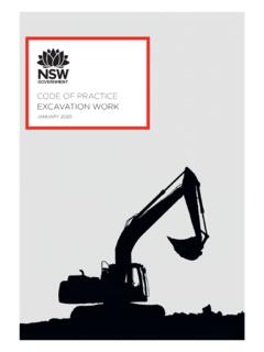
10 In either case, the support design must take into account the change in the stress field rather than the stand-up time of the excavation. Rock quality designation index (RQD) The Rock Quality Designation index (RQD) was developed by Deere (Deere et al 1967) to provide a quantitative estimate of rock mass quality from drill core logs. RQD is defined as the percentage of intact core pieces longer than 100 mm (4 inches) in the total length of core. The core should be at least NW size ( mm or inches in diameter) and should be drilled with a double-tube core barrel. The correct procedures for measurement of the length of core pieces and the calculation of RQD are summarised in Figure 1. Rock mass classification 4 Figure 1: Procedure for measurement and calculation of RQD (After Deere, 1989). Palmstr m (1982) suggested that, when no core is available but discontinuity traces are visible in surface exposures or exploration adits, the RQD may be estimated from the number of discontinuities per unit volume.