Transcription of Rocker Arm Geometry And Valvetrain Alignment
1 Rocker Arm Geometry And Valvetrain Alignment A Detailed Explanation Of Valvetrain Alignment Goals From the February, 2009 issue of Circle Track magazine By Bob Bolles Engine performance is like a complicated formula in which each individual part plays a role in the final answer. Some parts of the formula affect the final outcome more than others. The Valvetrain Geometry portion of the engine formula is one of those parts of the equation that can make a significant difference in power and durability. Here, we will try to fully explain how the components should work together and also how it can all go terribly wrong. Geometry in itself is a fairly complicated subject to master.
2 Many of us took classes in high school and/or college that dealt with this subject, but, as with many of our studies, we forgot the lessons as soon as the test was passed in. Who needs to know what will never be used in real life, right? For me, my early career involved heavy geometric calculations on a daily basis for over 20 years. So I will try to utilize that knowledge to explain, in an easy-to-understand way, what Valvetrain Geometry is all about. A lot of work goes into designing cam profiles for specific applications. The differences between cams in a particular type of racing are small and almost indistinguishable.
3 But the composition of the cam has a precisely defined purpose, and all that it is supposed to do for the valve is translated through the Valvetrain components. The cam design is directly affected by the Valvetrain Geometry (VTG). The industry is constantly searching for ways to design cam lobes, lifters, rockers, valve springs, and valves in a combination that will achieve better results for the intended uses. We, the racers, can take the best of the available parts and, through assembly errors, defeat all that has taken years to accomplish. Let's see how that is possible. The concept of correct Valvetrain Geometry has been around for a long time.
4 This is not just something that has arisen in the past few years, handed down from Nextel Cup, Indy Car, or Formula One racing. When I read Smokey Yunick's Power Secrets book years ago, he made a reference to how to achieve the correct Geometry , having learned the importance of that much earlier than the first copyright date of the book. Smokey didn't invent the method for correct VTG, he just explained it. We'll show you how this method still rings true today. Each and every major manufacturer of Valvetrain kits and Rocker arms has its own design parameters and design goals.
5 The approach and the dimensioning of components will necessarily differ with each manufacturer, even when the results are nearly the same. But, Geometry , being a finite resultant, necessitates that all systems hold to certain tolerances when it comes to correct VTG. One gentleman even went so far as to patent a precise geometric design called the Mid-Lift(r) system in 1982. Jim Miller saw the importance, as have others before and since, in maintaining correct Valvetrain geometric angles. We have spoken to Jim as well as some of the top manufacturers' technical leaders, and all of them are focused on their own geometric designs with specific goals.
6 The unstated goals, as each company maintains secrecy in this area of performance, differ from company to company. If any one of the many manufacturers out there is missing something major along these lines, I would be very surprised. That's not to say something couldn't be learned by all of us from a detailed presentation of how the Geometry works. As stated, each company has its own specific dimensioning of parts, matched components in Valvetrain sets, and so on. We are not here to tell anyone how to design components of the Valvetrain . We are also not here to critique any designs of VTG parts or combinations of those parts.
7 Lots of thought and testing goes into each and every company's designs, and the beauty of racing is that we are free to deviate from the norm at times to find hidden power and/or endurance. The problems we will address here arise when a builder assembles those parts incorrectly or assembles various part numbers that have not been designed to work together. This can happen very easily in the complicated process of fitting and assembling a race motor. There are so many critical dimensioning, balancing, fitting, and finessing processes involved in building a competitive racing motor, that it is not out of the question that something could be overlooked, such as ensuring correct VTG.
8 To achieve the optimum VTG, we must know how it works and why. We will use common logic and an understanding of early design goals used by Smokey and others as our starting point. We are going to provide data showing the results of different Geometry layouts that affect the amount of valve lift. It is not only the cam that regulates valve lift. The VTG has an effect, too. What has been alluded to in the past as well as the present is a view of the sweep of the Rocker tip across the end of the valve stem that conforms closely to maintaining the correct VTG. This only takes into consideration half of the Rocker arm Geometry to the valve side, and we'll cover the other side later.
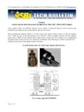
9 Here is what has been offered. It has been said that with a roller tip Rocker , the contact point with the valve stem should, at the beginning of the valve opening cycle, move toward the exhaust side of the head, reach an apex at approximately mid-cycle, and then move back toward the intake side of the head to about the same position as when the cycle started as the valve becomes fully opened. If this occurs, then the Geometry is necessarily a certain configuration and cannot be any other way. In Geometry , when this occurs, the angle formed by a line through the Rocker shaft axis and the roller axis is at or very near 90 degrees to the valve stem when the valve is at the mid point in its travel toward full open position.
10 Miller stated as the patented goal of his Mid-Lift(r) system that the angle at mid-lift would be exactly 90 degrees. Opinions vary on that point, but few would disagree that deviating too far from this concept is not advantageous. By positioning the Rocker arm height in a certain way, the contact sweep path may or may not be centered on the valve stem. In a perfect world, this would be the case. But there are variations in the machining of the blocks, placement of the Rocker studs, rotational length of different Rocker arms, and lengths of the valves that will alter slightly the position of the Rocker tip sweep path on the end of the valve stem.