Transcription of Roof Structures - UnitCare
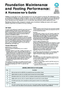
1 roof STRUCTURESR oofsSECTION1 MODULE 3 SHEET 5 SECTIONSECTION11 MODULESHEETSECTION12 roof StructuresTypes of roof structureTraditional roofs can be divided into three main types of structure : Single roofs. Double roofs. Trussed construction methods make use of another type of roof structure and this is known as trussed rafter roofs (see trussed rafter roofs).Trussed roofSingle roofDouble roofTrussed rafter roofROOF STRUCTURESR oofsSECTION12 MODULE 3 SHEET 6 Single roofsRafters of single roofs do not require any intermediate support. This type of roof has a number of limitations. It can only be used for small spans. If greater spans are required, larger roof sections would be needed.
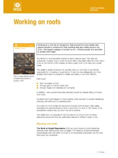
2 If the feet of the rafters are not tied together by means of a binder or roof joist, then this type of roof will have a tendency, under weight, to push the supporting walls outwards at the top causing structural failure of the roofs can be categorised as follows:Couple roof These can be used for building with a clear span of not greater than 3m and pitches less than 40 .Collar roof These can be used for buildings with a clear span not exceeding couple roof These can be used for buildings with a clear span not exceeding and with pitches less than 25 .Couple roofThis type of roof structure is very limited in its use. The roof consists of common rafters fi xed at the ridge and at the wall plate.
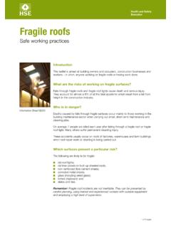
3 When subjected to any type of load or force acting vertically downwards the rafters will move outwards at their feet thus exerting thrust to the walls forcing them outwards and causing possible failure of the wall roofCouple roof under pressureROOF STRUCTURESR oofsSECTION1 MODULE 3 SHEET 7 SECTIONSECTION11 MODULESHEETSECTION12 Collar roofA collar roof incorporates a horizontal roof member positioned approximately one third of the distance from the ridge to the wall plate line. This extra roof member helps prevent the rafters from spreading when under load; this allows this type of roof structure to be used for greater spans than the couple roof . This design also gives a greater ceiling height if couple roofThis roof incorporates a main tie which is secured to the feet of each rafter and spans the width of the building.
4 This added member forms a triangle which introduces the triangulation of forces within the structure . To stop the ceiling joist from sagging, a hanger is fi xed to the rafter at the top and the ceiling joist at the bottom. To further increase the strength of this structure , a binder is fi xed to each ceiling joist and hanger. This binder runs parallel with the main wall and at right angles to the ceiling type of structure ensures that this type of roof can be used for great spans without the fear of the roof spreading under roofClose couple roofROOF STRUCTURESR oofsSECTION12 MODULE 3 SHEET 8 Pitches, Spans and RisesWhen setting out a roof , there are certain essential factors that must be considered.
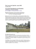
5 These are: roof span This is the distance across the roof and measured to the outer edges of the wall plates. roof height or rise This is the vertical height of the roof at its highest point and is measured from the top of the wall plates to the intersection of the rafters at the top of the roof . When measuring rafters, the length is taken as a straight line running through the centre of the rafter. roof pitch This is the angle or slope of the roof and can be expressed in degrees or as a fraction or ratio found by dividing the rise by the If a roof has a span of 6m and a rise of 3m then the pitch would be: Rise 3 1 Pitch = Span = 6 = 2 pitchSince the rise is half the span, the angle of the roof would be 45.
6 Defi nitions of terminology of a gable roofROOF STRUCTURESR oofsSECTION1 MODULE 3 SHEET 9 SECTIONSECTION11 MODULESHEETSECTION12 Common Rafter Length and BevelsWhen determining the lengths and bevels of common rafters, it is normal to consider them as single lines rather than rafters of a certain width or thickness. If the rise and the span are known, it is a simple procedure to determine the length of the common rafter and its main roof section can be set out full size or to scale. Once the section has been set out the length of the common rafter can be determined by drawing the rise and the span as a right angle joined together by the hypotenuse which will determine the slope of the rafter is seated upon the wall plate by means of a notch or birdsmouth joint which is cut one third into the rafter.
7 The angle at which the notch is cut is called the seat cut. The top angle or bevel is called the plumb the bevels have been determined, a sliding bevel can be set to the angle required or in some cases, a piece of plywood can be cut to each bevel and used as a template for all the other determining the length of the rafter, an allowance is made for the thickness of the ridge and the length of the overhang at the the length and bevels of a common rafterROOF STRUCTURESR oofsSECTION12 MODULE 3 SHEET 10 Verge Details and Ladder FrameThe construction of the verge of a gable roof is shown below. The roof extends over the gable wall to give a suitable overhang.
8 To achieve this is a simple frame called a ladder frame is constructed. This frame consists of the last two rafters joined together by means of noggings nailed to the inside of the rafters. The brickwork of the gable extends through this frame to fi nish the wall level with the top of the fi nishing trim called a barge board is then nailed to the last rafter. This barge board is suffi ciently wider than the rafters to cover the entire end rafter including the tilting fi soffi t is then fi xed to the underside to match the soffi t under the eaves. The barge board is also fi xed to the fascia. The fascia can be mitred to the barge board at the foot while the top of the barge board at the apex of the roof is mitred to the matching barge board on the other STRUCTURESR oofsSECTION1 MODULE 3 SHEET 11 SECTIONSECTION11 MODULESHEETSECTION12 Eaves Details and FasciasThere are various ways of constructing the eaves of a gable roof .
9 Below are two examples: Flush eaves. Boxed or closed eaves detailsClosed or boxed eaves detailsROOF STRUCTURESR oofsSECTION12 MODULE 3 SHEET 12 Flush eavesIn this method of fi nishing off the lowest edge of the roof , the rafter feet are cut plumb, and project 25mm from the face of the outer brickwork. This will allow a ventilation gap to be formed so that a continuous fl ow of air can circulate throughout the roof fascia board is nailed directly to the rafter feet to form a face trim. It is to this fascia board that the guttering is fi or boxed eavesThis is a more complex method of fi nishing the lowest edge of the roof . The rafter feet are allowed to overhang the face of the outer brickwork.
10 The overhang can vary in size but usually the distance is stipulated on the working drawings, or is at a distance that can accommodate a proprietary ventilation soffi soffi t is supported by a cradling bracket or, in some cases, a piece of plywood cut to roof space can be ventilated by using a proprietary vermin proof ventilation strip or the soffi t can be drilled with a series of holes into which plastic ventilators are fi ventilationRoof ventilation is essential to reduce the likelihood of condensation within the roof space as required by the Building Regs regulations state that all roofs must be cross-ventilated at eaves level by permanent vents and these must have an equivalent area equal to a continuous gap along both sides of the roof of 10mm, or 25mm where the pitch of the roof is less than 15.