Transcription of ROSE NAV ARC NAV-Wx Radar
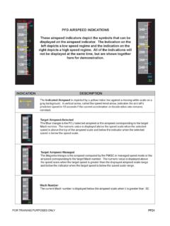
1 ND1 FOR TRAINING PURPOSES ONLYThe ND, positioned inboard of the PFD, is independently controlled by the captain and first are five modes available for display: rose NAV, rose ILS, rose VOR, ARC and ILSROSE VORROSE NAVARC NAV-Wx RadarPLANILS APPGS TAS257 286120/25 VESTI260 37NM23 APPGS TAS257 288120/25 VESTI260 37NM23 APPGS TAS257 288120/25 VESTI260 37NM23 332040 SWENGLOWFESTIGXVRBVDILS APPGS TAS483 451210/45 VOR 1 OOD M22 NMVOR 2 DOONM---ILS APPGS TAS138 145140 ' 45"ND2 FOR TRAINING PURPOSES ONLYN avigation Display (ND)INFORMATION COMMON TO ALL MODES INDICATION DESCRIPTIONILS APPRNAV APPR ange Scale Each mode is capable of displaying a range scale from 10 to 320 NM, selected on the respective Captain sor First Officer s EFIS control panel.
2 The maximum range from the aircraft position in the rose mode is half the selected range. In the ARC mode, the range from the aircraft position to the outer edge of the scale is equal to the selectedrange. The range scale will be indicated on the ND display by white dashed circular lines with blue Symbol/Cross Track Error This Aircraft Symbol indicates the current position and appears in the center of the NDin the rose mode, at the bottom of the display in the ARC mode, and along the route atthe appropriate location in the PLAN mode. The Cross Track Error, the lateral deviation left or right of the active flight plan course, willbe displayed next to the aircraft symbol in nautical Heading The yellow line displays the aircraft s magnetic heading on the moving white compassrose.
3 Small white triangles are fixed at 45 intervals on the compass rose . TRU appears at the top of the compass rose if the display has changed from magneticheading to true heading. The FCU selected heading appears as a blue triangle on the heading scale. A green diamond below the appropriate track identifies the actual aircraft ground speed and true airspeed are displayed in the upper left-hand corner on the information is furnished by the ADIRS. The ground speed is operative on the ground and can assist in monitoring taxi speed. The wind direction and speed are displayed below the GS and TAS. The digital indication is based on true north. The wind arrow indicates the wind direction based on magnetic wind arrowwill appear when the velocity is greater than 2 messageThe type of approach selected form the MCDU database, if any, is indicated in the top centerof the TRAINING PURPOSES ONLYW aypoint/Navaid InformationThe upper right-hand corner of the ND will display navaid or waypoint information dependingon the ND mode selection.
4 When rose NAV ILS mode is selected, the ILS frequency course and identifiers aredisplayed. When rose NAV VOR is selected, the VOR frequency, selected course, and identifierare displayed. In rose NAV, ARC or PLAN modes, the TO waypoint is displayed in the upper right-hand corner along with the track, distance, and Information Each ND has an independent chronometer controlled by a CHRONO pb. The display willappear and begin timing when the pb is pressed once. The indication is in minutes andseconds from 0 to 59' 59" in hours and minutes from 1 H to 99 H 59'. The elapsed time will stop when the CHRONO pb is pressed a second time and thedisplay will be removed when CHRONO is pressed a third InformationWhen the VOR selector switch on the Captain s of First Officer s EFIS control panel is set toVOR, the respective ND displays the bearing pointer and the following navaid information: Type of navaid (VOR).
5 A single line bearing pointer for VOR 1 and a double line bearing pointer for VOR 2. Navaid identification if the navaid is tuned. If the navaid is not tuned, the navaid fre-quency is displayed. DME. Mode of tuning: Nothing for a station tuned automatically by the FMGC. M for a for manually tuned navaid on the MCDU RAD NAV page. R for a remotely tuned navaid through the RMP. This procedure is used in the eventof a failure of both FMGCs or MCDUs. If the navaid signal is lost, the ND stops displaying the associated data except for theidentification or frequency. INDICATION DESCRIPTIONND4 FOR TRAINING PURPOSES ONLY INDICATION DESCRIPTIONROSE and ARC NAV MODES rose and ARC modes provide the same information except the ARC mode provides only a 90 compass roseview.
6 NAV Mode SymbolsPosition where the aircraft will level-off at the FCU selected altitude. The same symbol willindicate a level-off from a managed climb (CLB) or selected climb (OP CLB).Position where the aircraft will level-off at the constrained altitude entered in the MCDU. Themanaged CLB mode must be engaged for the altitude constraint symbol to appear and where the aircraft will level-off at the FCU selected altitude. The same symbol willindicate a level-off from a managed decent (DES) or selected descent (OP DES).Position where the aircraft will level-off at the constrained altitude entered in the MCDU. Themanaged DES mode must be engaged for the altitude constraint symbol to appear and of climb with the CLB mode of climb with the CLB mode not of Descent or continue descent with DES of Descent or continue descent with DES not point where the aircraft is predicted to intercept the FMGS computed vertical descentprofile.
7 The indicator is blue indicating the DES mode is point where the aircraft will meet the FMGS computed vertical profile. The indicator iswhite indicating the DES mode is not engaged. Flight Plan Waypoint FMGC Database Waypoint: Displayed when the waypoint pb is pressed on the EFIS controlpanel. TO Change Indicates the point where the aircraft will initiate an automatic acceleration or decelerationfrom current speed to new computed speed in case of SPD LIM, SPD CSTR, or HOLDINGSPD (including 250 knots below 10,000).Deceleration Point Indicates where the aircraft will initiate an automatic deceleration toward VAPP. Managed NAV mode and managed speed must be TRAINING PURPOSES ONLY* KPHL* KPIT INDICATION DESCRIPTIONA ltitude Constraints Constraint is predicted to be met when the aircraft is in managed lateral and verticalmodes.
8 Constraint is predicted to be missed. In this situation the aircraft is in the managedlateral and vertical modes; however, the FMGC will not be able to meet the altitudeconstraint. Constraint is not being considered by the Plan Routes The NAV modes can display the following flight plans. A green line represents the Active Flight Plan. Managed Mode: The course line will be continuous and depict the waypoints inrange that are yet to be overflown. When the range selector is set to 160 or 320 NM, only the first waypoint ofa SID or the last waypoint of a STAR will be depicted. A continuous blue line depicts the Missed Approach Procedure. A dashed blue line depicts the Alternate Flight Plan until activated.
9 Onceactivated, the alternate flight plan is displayed in green. If a flight plan offset is entered, the original flight plan course will be adashed green line and the offset course will be depicted as a continuousgreen line. Note: When flying an ILS approach the ND course will be depicted as acontinuous green line; however, course guidance is being provided by thelocalizer signal. The FMA must be referenced to determine the activenavigation mode. Selected Mode: If HDG is selected (FCU HDG knob pulled) the active flight planline will be dashed. When the HDG mode active with NAV armed to intercept the FMGC course, the ND will display the new active flight plan as a continuous greenline once the FMGC has computed the intercept.
10 The portion of the flightplan before the intercept, that will not be flown will be shown as a dashedline. A continuous white line depicts the Secondary Flight Plan. The ND will continueto display the active flight plan and where common legs occur, the course line willbe a continuous green line. A dashed yellow line represents th Temporary Flight Airports included in flight plan: If the runway is specified in the flight plan (departure or destination) it isrepresented by the oriented runway symbol in white. If the runway is not specified in the flight plan it is represented by a star and theidentification is displayed in white. The magenta star represents the airports that are displayed by pressing the APRTSpb on the EFIS control Marker Beacon (Diamond Shape) Outer marker Middle marker Inner markerND6 FOR TRAINING PURPOSES ONLY INDICATION DESCRIPTIONN avaidsThe ND can display: TACAN/DME VOR VOR/DME NBD navaids from the database.