Transcription of Rosemount 3051SFP Proplate Flowmeter - FMTECH
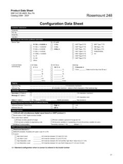
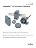
1 Product data Sheet00813-0100-4686, Rev LACatalog 2006 - 2007 Rosemount Integral Orifice Flowmeter Series4 Rosemount 3051 SFP Proplate FlowmeterSPECIFICATIONSP erformanceRepeatability Sizes 1/2-in. (15 mm) 1-in. (25 mm) 11/2-in. (40 mm) Performance Statement Assumptions Use associated piping. Electronics are trimmed for optimum flow accuracySizingContact a Emerson Process Management sales representative for assistance. A Configuration data sheet is required prior to order for application Liquid Gas Steam 4 20 mA/HART Zero and Span AdjustmentZero and span values can be set anywhere within the must be greater than or equal to the minimum 4 20 mA is user-selectable for linear or square root output.
2 Digital process variable superimposed on 4 20 mA signal, available to any host that conforms to the HART SupplyExternal power supply required. Standard transmitter (4 20 mA): to V dc with no load3051S SIS Safety transmitter: 12 to 42 Vdc with no load3051S HART Diagnostics transmitter: 12 to 42 Vdc with no loadSystem Reference Accuracy Percentage (%) of volumetric flow rate(1)(1) Without associated straight run piping, discharge coefficient uncertainty can add up to - 5% additional error. Consult the factory for additional ( )(2)(2) = Orifice Plate Borebody (8:1 flow turndown)Ultra (8:1 flow turndown)Ultra for Flow (10:1 flow turndown) < < < < < < < data Sheet00813-0100-4686, Rev LACatalog 2006 - 20075 Rosemount Integral OrificeFlowmeter SeriesLoad Limitations Maximum loop resistance is determined by the voltage level of the external power supply, as described by.
3 HART Diagnostics Suite (Option Code DA1)The 3051S HART Diagnostics Transmitter provides Abnormal Situation Prevention (ASP) indication, device operating hours, variable logging, loop output readback diagnostic, and enhanced EDDL graphic displays for easy visual integral statistical process monitoring (SPM) technology calculates the mean and standard deviation of the process variable 22 times per second and makes them available to the user. The 3051S ASP algorithm uses these values and highly flexible configuration options for customization to detect many user-defined or application specific abnormal situations ( plugged impulse line detection).
4 The device operating hours are logged along with the occurrence of diagnostic events to enable quick troubleshooting of application and installation fieldbusPower SupplyExternal power supply required; transmitters operate on to V dc transmitter terminal mA for all configurations (including LCD display option)FOUNDATION fieldbus ParametersStandard Function BlocksResource Block Contains hardware, electronics, and diagnostic Block Contains actual sensor measurement data including the sensor diagnostics and the ability to trim the pressure sensor or recall factory Block Configures the local Analog Input Blocks Processes the measurements for input into other function blocks.
5 The output value is in engineering or custom units and contains a status indicating measurement Block with Auto-tune Contains all logic to perform PID control in the field including cascade and feedforward. Auto-tune capability allows for superior tuning for optimized control Link Active Scheduler (LAS)The transmitter can function as a Link Active Scheduler if the current link master device fails or is removed from the Upgrade in the FieldSoftware for the 3051S with FOUNDATION fieldbus is easy to upgrade in the field using the FOUNDATION fieldbus Common Device Software Download AlertsEnable the full power of the PlantWeb digital architecture by diagnosing instrumentation issues, communicating advisory, maintenance, and failure details, and recommending a Control Function Block Suite (Option Code A01)
6 Input Selector Block Selects between inputs and generates an output using specific selection strategies such as minimum, maximum, midpoint, average, or first good. Arithmetic Block Provides pre-defined application-based equations including flow with partial density compensation, electronic remote seals, hydrostatic tank gauging, ratio control and Characterizer Block Characterizes or approximates any function that defines an input/output relationship by configuring up to twenty X, Y coordinates. The block interpolates an output value for a given input value using the curve defined by the configured Bock Compares the integrated or accumulated value from one or two variables to pre-trip and trip limits and generates discrete output signals when the limits are reached.
7 This block is useful for calculating total flow, total mass, or volume over TransmitterMaximum Loop Resistance = * (Power Supply Voltage )The HART communicator requires a minimum loop resistance of 250 for SIS Safety Transmitter (output code B) 3051S HART Diagnostics Transmitter (option code DA1)Maximum Loop Resistance = * (Power Supply Voltage )The HART communicator requires a minimum loop resistance of 250 for (V dc)Load (Ohms) (V dc)Load (Ohms) Entries14 (max.)Links30 (max.)Virtual Communications Relationships (VCR) 20 (max.)Product data Sheet00813-0100-4686, Rev LACatalog 2006 - 2007 Rosemount Integral Orifice Flowmeter Series6 Output Splitter Block Splits the output of one PID or other control block so that the PID will control two valves or other Selector Block Selects one of up to three inputs (highest, middle, or lowest) that are normally connected to the outputs of PID or other control function Compensated Mass Flow Block (Option Code H01)Calculates fully compensated mass flow based on differential pressure with external process pressure and temperature measurements over the fieldbus segment.
8 Configuration for the mass flow calculation is easily accomplished using the Rosemount 3095 Engineering fieldbus Diagnostics Suite (Option Code D01)3051S FOUNDATION fieldbus Diagnostics provide Abnormal Situation Prevention (ASP) indication and enhanced EDDL graphic displays for easy visual integral statistical process monitoring (SPM) technology calculates the mean and standard deviation of the process variable 22 times per second and makes them available to the user. The 3051S ASP algorithm uses these values and highly flexible configuration options for customization to detect many user-defined or application specific abnormal situations ( plugged impulse line detection).
9 Process Temperature LimitsDirect Mount Electronics 40 to 450 F (40 to 232 C)Remote Mount Electronics 148 to 850 F ( 100 to 454 C)(1)Electronics Temperature LimitsAmbient 40 to 185 F ( 40 to 85 C) With Integral Mount LCD Display: 4 to 175 F ( 20 to 80 C)Storage 50 to 230 F ( 46 to 110 C) With Integral Mount LCD Display: 40 to 185 F ( 40 to 85 C)Pressure Limits(2) Direct Mount Electronics Pressure retention per ANSI 600# or DIN PN Static Pressure Limits Range 1A: Operates within specification between static line pressures of psia to 2000 psig ( to 138 bar) Ranges 2A 3A: Operates within specifications between static line pressures of psia and 3626 psig ( bar-A to 250 bar-G)Burst Pressure LimitsCoplanar or traditional process flange 10000 psig (689,5 bar).
10 Overpressure LimitsFlowmeters withstand the following limits without damage: Range 1A: 2000 psig (138 bar) Ranges 2A 3A: 3626 psig (250 bar)Humidity Limits 0 100% relative humidityTurn-On TimePerformance within specifications less than 2 seconds (typical) after power is applied to the transmitterDampingAnalog output response to a step input change is user-selectable from 0 to 60 seconds for one time constant. This software damping is in addition to sensor module response timeFailure Mode AlarmHART 4-20mA (output option codes A and B)If self-diagnostics detect a gross transmitter failure, the analog signal will be driven offscale to alert the user.