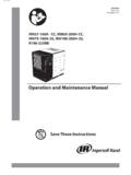
Transcription of ROTARY SCREW COMPRESSOR UNITS - Johnson Controls
1 Form (NOV 2014). installation - OPERATION - maintenance . File: SERVICE MANUAL - Section 70. Replaces: (AUG 2014). Dist: 3, 3a, 3b, 3c RWF II. ROTARY SCREW COMPRESSOR UNITS . ALL REFRIGERANTS. MODELS. 100 through 1080. THIS MANUAL CONTAINS RIGGING, ASSEMBLY, START-UP, AND maintenance INSTRUCTIONS. READ THOROUGHLY. BEFORE BEGINNING installation . FAILURE TO FOLLOW THESE. INSTRUCTIONS MAY RESULT IN PERSONAL INJURY OR DEATH, DAMAGE TO THE unit , OR IMPROPER OPERATION. Please check for the latest version of this publication. (NOV 14) RWF II ROTARY SCREW COMPRESSOR UNITS . Page 2 installation - OPERATION - maintenance . Contents General Information maintenance 3 General 25.
2 Design 3 Normal maintenance 25. Job 3 General 25. Transit Damage 3 COMPRESSOR Shutdown And 25. unit 3 General Instructions For Replacing. COMPRESSOR 4 COMPRESSOR unit 25. Oil Filter (OF 1) Cartridge 26. installation Strainer Demand Oil 27. 5 Strainer Liquid 27. Rigging And 5 Coalescer Filter Element(s).. 27. Skid 5 Changing 27. Checking Motor/ COMPRESSOR 6 Demand Pump 28. COMPRESSOR /Motor Coupling 6 Demand Pump 29. Oil Pump 7 Thrust Bearing 30. Holding Charge And 7 installation Of Carbon Graphite 30. Oil 7 Troubleshooting The Demand 30. Oil Heater(s).. 8 Preventive 31. Oil Filter(s).. 8 maintenance 32. Suction Valve 8 Recommended maintenance 32. Thermosyphon Oil 8 Vibration 32.
3 Liquid Injection Oil Cooling (Optional).. 9 Oil Quality And 33. Water-Cooled Oil Cooling (Optional).. 10 Oil Sampling 33. Economizer High Stage (Optional).. 10 Operating 33. Economizer Load 11 Motor 33. 12 Grease 34. Motor Starter 12 Troubleshooting 34. Current Transformer (CT) 13 Abnormal Operation Analysis And 34. Minimum Burden 14 Servicing The Cold-Start 35. control Power 14 Pressure Transducers 36. Operation Pressure Transducers 36. Capacity Linear Transmitter Slide 37. Operation And Startup 15 Volume Ratio control Transmitter Slide 37. SGC 15 Temperature 38. COMPRESSOR Lubrication 15 Oil Level 38. No Pump Oil 15 Troubleshooting the RWF II 39. Demand Pump Oil 16 Troubleshooting The Demand Pump 39.
4 COMPRESSOR Oil Separation 16 Troubleshooting The Oil Separation 40. Cold-Start 16 Troubleshooting The Hydraulic 40. COMPRESSOR Hydraulic 17 Motor And Bare COMPRESSOR 41. Volume Ratio 17 Shutdown Due To Improper Oil Pressure . COMPRESSOR Oil Cooling 17 (High Stage And Booster).. 41. Single-Port Liquid 18 SAE Straight Thread O-Ring Fittings . Dual-Port Liquid 18 Assembly 41. Quantum HD EZ-COOL Liquid Injection Adjustment COMPRESSOR Port 42. 19 P & I 50. Operation Of Danfoss Liquid Injection 20. Suction Check Valve 23 installation Of Electronic Equipment Low Ambient 23 Wire 53. Suction Check Valve Power Assist 23 Voltage 53. Balance Piston Pressure 23 54.
5 Initial 24 VFD 54. Initial Start-Up 24 55. Normal Start-Up 24 Wiring 55. VFD Skip 24 57. UPS Power and Quantum HD 57. Forms Operating Log 58. RWF II COMPRESSOR Prestart 59. Vibration Data 64. 65. RWF II ROTARY SCREW COMPRESSOR UNITS (NOV 14). GENERAL INFORMATION Page 3. General Information Job Inspection Immediately upon delivery examine all crates, boxes and Preface exposed COMPRESSOR and com ponent surfaces for dam age. This manual has been prepared to acquaint the owner and Unpack all items and check against shipping lists for any serviceman with the installation , OPERATION, and MAIN discrepancy. Examine all items for damage in transit. TEN ANCE procedures as recommended by Johnson Controls for Frick RWF II ROTARY SCREW Compres sor UNITS .
6 Transit Damage Claims All claims must be made by consignee. This is an ICC re . For information about the functions of the Quantum HD. quirement. Request immediate inspection by the agent of control panels, communications, specifications, and wiring the carrier and be sure the proper claim forms are execut ed. diagrams, see publication series , , , and Report damage or shortage claims im mediately to Johnson Controls Inc., Frick Sales Ad ministration Depart ment, in It is most important that these UNITS be properly applied to an Waynes boro, PA. adequately controlled refrigeration system. Your authori zed Frick representative should be con sulted for their expert unit Identification guidance in this determination.
7 Each COMPRESSOR unit has 2 identifica tion data plates. The Proper performance and continued satisfaction with these COMPRESSOR data plate containing COMPRESSOR model and UNITS is dependent upon: serial number is mounted on the COMPRESSOR body. The CORRECT installation unit data plate containing unit model, serial number and PROPER OPERATION Frick sales order number is mounted on the side of the REGULAR, SYSTEMATIC maintenance Quantum HD control panel. To ensure correct installation and application, the equip ment must be properly selected and connected to a properly de NOTICE. signed and installed system. The Engi neering plans, piping When inquiring about the compres sor or unit , or order- layouts, etc.
8 Must be detailed in accor dance with the best ing repair parts, provide the MODEL, SERIAL, and FRICK . practices and local codes, such as those outlined in ASHRAE SALES ORDER NUMBERS from these data plates. literature. A refrigeration COMPRESSOR is a VAPOR PUMP. To be certain that it is not being subjected to liquid refriger ant carryover it is necessary that refriger ant Controls are carefully selected and in good operating condition; the piping is properly sized and traps, if necessary, are correct ly arranged; the suction line has an accumulator or slugging protec tion; that load surges are known and provisions made for control ; operating cycles and de frost ing periods are reasonable; and that high side condensers are sized within system and COMPRESSOR design limits.
9 It is recommended that the entering vapor temperature to the COMPRESSOR be superheated to 10 F above the refriger ant saturation temperature. This assures that all refrigerant at the COMPRESSOR suction is in the vapor state. Design Limitations The COMPRESSOR UNITS are designed for operation within the pressure and temperature limits as shown in Frick publica . tion unit DATA PLATE. SAFETY PRECAUTION DEFINITIONS. Indicates an imminently hazardous situation which, if not avoided, will result in death or serious DANGER injury. Indicates a potentially hazardous situation or practice which, if not avoided, will result in death or WARNING serious injury. Indicates a potentially hazardous situation or practice which, if not avoided, will result in damage CAUTION to equipment and/or minor injury.
10 NOTICE Indicates an operating procedure, practice, etc., or portion thereof which is essential to highlight. (NOV 14) RWF II ROTARY SCREW COMPRESSOR UNITS . Page 4 GENERAL INFORMATION. COMPRESSOR Identification Each COMPRESSOR has an identification data plate (see below), containing COMPRESSOR model and serial number mounted on the COMPRESSOR body. COMPRESSOR DATA PLATE. ROTARY SCREW COMPRESSOR serial numbers are defined by the following information: EXAMPLE: 10240A90000015Z. GLOBAL ADDITIONAL. PLANT DECADE MONTH YEAR SEQ NO. REMARKS. 1024 0 A 9 0000015 Z. Month: A = JAN, B = FEB, C = MAR, D = APR, E = MAY, F =. JUN, G = JUL, H = AUG, K = SEP, L = OCT, M = NOV, N = DEC.