Transcription of Rotor Balancing Tutorial
1 Copyright 2016 by Turbomachinery Laboratory, Texas A&M Engineering Experiment Station 1 Rotor Balancing Tutorial Ray Kelm, Owner/Chief Engineer Kelm Engineering, LLC Friendswood, TX, USA Dustin Pavelek, Consulting Engineer Kelm Engineering, LLC Friendswood, TX, USA Walter Kelm, Graduate Engineer Kelm Engineering, LLC Friendswood, TX, USA Ray Kelm, is owner and Chief Engineer of Kelm Engineering, LLC located in Friendswood, Texas. The company specializes in numerical modeling and field testing of dynamic systems including rotating and reciprocating machinery as well as piping systems and other equipment. He has 30+ years of experience in the oil & gas, power, manufacturing and petrochemical industries.
2 He holds a in Mechanical Engineering from Texas A&M University and a in Mechanical and Aerospace Engineering from the University of Virginia. He is a registered professional engineer in the State of Texas, a member of the Vibration Institute Board of Directors, and ASME. Walter Kelm is a Graduate Engineer with Kelm Engineering, LLC where he is responsible for conducting analytical modeling and field testing for rotating and reciprocating machinery. He holds a in Mechanical Engineering from Rice University. Walter is certified as an Engineer-in-Training and is a certified ISO Category IV Vibration Analyst through the Vibration Institute.
3 Dustin Pavelek is a Consulting Engineer with Kelm Engineering, LLC where he is responsible for conducting analytical studies and field vibration testing for rotating and reciprocating machinery. He previously served as a member of corporate Machinery Engineering and PdM groups in the petrochemical and power generation industries. He is a proud graduate of Texas A&M University and holds a and an in Mechanical Engineering. Pavelek is a registered professional engineer in the States of Texas and Louisiana and is a Certified ISO Category IV Vibration Analyst through the Vibration Institute. ABSTRACT The purpose of this Tutorial is to describe details related to shop and field Balancing of turbomachinery.
4 The target machinery is API type turbomachinery such as steam turbines, compressors, and other rotating machinery that is common in refining and petrochemical plants. An introduction to shop Balancing includes a review of current practice as it relates to shop Balancing of API rotors. Included in the description and discussion is a review of API shop Balancing methods as well as a review of ISO standards related to shop and field Balancing that are referenced by API standards. Greater emphasis is presented in this Tutorial on field Balancing , which applies to balance correction in situ on rotating machinery and similarly applies to methods and techniques used when conducting high speed shop Balancing .
5 Copyright 2016 by Turbomachinery Laboratory, Texas A&M Engineering Experiment Station 2 INTRODUCTION Rotor unbalance is a common cause of synchronous Rotor vibration that is detected using non-contacting proximity probes or with bearing housing vibration. The causes of unbalance can be varied with the actual causes depending on manufacturing methods and procedures, repair practices, as well as balance condition changes during operation. Some operational causes of unbalance include Rotor fouling (dirt or other deposits on the Rotor ), bowing of rotors due to uneven heating or shaft damage, loss of Rotor material possibly from rubs, or other causes.
6 Balance correction is most effective when it is applied at or on the component that actually has the unbalance. In most cases the Rotor is manufactured from a number of components (impellers, balance disks, thrust collars, etc.) that will each have some level of unbalance during assembly of the Rotor . During operation, the unbalance state of each mounted component could change due to reasons stated above. As a result, the actual balance condition of an assembled Rotor is never fully known prior to, during, or after a successful balance procedure is executed either in the shop or field. DEFINITION OF UNBALANCE Unbalance will occur any time a Rotor or a component mounted on a Rotor has a mass center (or center of gravity, cg.)
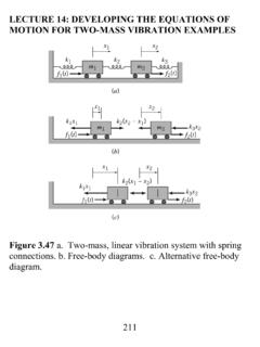
7 That is not coincident with the axis of rotation. When this occurs, a force is generated due to rotation of the shaft that is defined by the following equation and shown graphically in Figure 1: = 2 Where = = = = , /sec= 2 60 = , Figure 1 - Unbalance Force This force rotates about the shaft that is phased to the shaft which results in vibration at 1xRPM. It is possible to measure the dynamic force in a balance machine, but not possible when operating the machine on the Rotor support bearings as is the case for either high speed shop Balancing or field Balancing .
8 As the machine operates, the balance condition of the Rotor or components on the Rotor can x + Fbalance + Fbalance + Fbalance Force rotates in phase with the shaft Funbalance + x e Center of shaft rotation Center of mass (center of gravity, ) Machine housing Rotation Copyright 2016 by Turbomachinery Laboratory, Texas A&M Engineering Experiment Station 3 be evaluated at least in part by measuring and assessing the vibration characteristics of the machine. Many other machine faults also produce vibration at 1xRPM such as bearing or shaft misalignment, loose components, rubs, or a host of other sources. There are two general conventions for defining an amount of unbalance for a component or a shaft including eccentricity and unbalance magnitude.
9 Both conventions can be used to define or describe the balance state of a component or a shaft and are often used interchangeably. The term balance eccentricity, or permissible residual specific unbalance as detailed in ISO 1940 (see References), is defined by the amount of unbalance present divided by the mass of the Rotor or component. When this term is used, it can be physically related to the runout of a previously balanced component as follows: = = 2 = = = = In more detail, the balance of a component can be defined either by the mass of the component and the amount of unbalance (M and U), or by the mass and the eccentricity (M and e).
10 This distinction is helpful for the purpose of understanding and evaluating the significance of how components are attached to a shaft. In particular, API 617 defines that individual components should be individually dynamically balanced before assembly to ISO 1940 G1 levels. For a component that is installed on a 5000 RPM shaft, the allowable eccentricity (e) at G1 is mm ( ), or mils TIR. Consistently maintaining less than mils TIR for mounted components on most shafts for industrial machinery will be impractical, making the mounting process a likely larger contributor to the resulting unbalance of the mounted component than the balance condition of the part itself.