Transcription of RP/IS-909S Installation, Maintenance, & Repair …
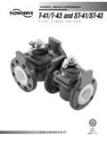
1 RP/IS-909 SNo. 909QT-S 11 2" shownNOTICEI nquire with governing authorities for local installation requirements NOTICEFor Australia and New Zealand, line strainers should be installed between the upstream shutoff valve and the inlet of the backflow important that this device be tested periodically in com-pliance with local codes, but at least once per year or more as service conditions warrant. If installed on a fire sprinkler system, all mechanical checks, such as alarm checks and backflow preventers, should be flow tested and inspected internally in accordance with NFPA 13 and NFPA , maintenance , & Repair Series 909 and LF909 Reduced Pressure Zone AssembliesSizes: 3 4" 2" (20-50mm)Local building or plumbing codes may require modifications to the information provided.
2 You are required to consult the local building and plumbing codes prior to installation . If this information is not consistent with local building or plumbing codes, the local codes should be for Periodic Inspection/ maintenance : This product must be tested periodically in compliance with local codes, but at least once per year or more as service conditions warrant. Corrosive water conditions, and/or unauthorized adjustments or Repair could render the product ineffective for the service intended. Regular checking and cleaning of the product s internal components helps assure maximum life and proper product function. WARNING!Read this Manual BEFORE using this to read and follow all safety and use information can result in death, serious personal injury, property damage, or damage to the this Manual for future field testing procedure, refer to Watts installation sheets IS-TK-DP/DL, IS-TK-9A, IS-TK-99E and IS-TK-99D found on other Repair kits and service parts, refer to our Backflow Prevention Products Repair Kits & Service Parts price list PL-RP-BPD found on technical assistance, contact your local Watts representative.
3 1. Backflow preventers must be installed in high-visibility locations in order to allow for immediate notice of telltale discharge or other malfunction. This location should also facilitate testing and servicing, and protect against freezing and vandalism. 2. Installing a backflow preventer in a pit or vault is not recom-mended as flooding of the pit will cause a crossconnection. Ensure that all local codes and required safety provisions are met. An air gap below the relief port must be maintained so as to avoid, flooding and submersion of the assembly, which may lead to a cross-connection. 3. A strainer should be installed ahead of the backflow preventer to protect all internal components from unnecessary fouling.
4 CAUTION!Do not install a strainer ahead of the backflow preventer on seldom-used, emergency water lines ( fire sprinkler lines). The strainer mesh could potentially become clogged with debris present in the water and cause water blockage during an emergency. 4. Normal discharge and nuisance spitting are accommodated by the use of a Watts air gap fitting and a fabricated indirect waste line. Floor drains of the same size MUST be provided in case of excessive discharge. 5. When a 909 and LF909 Series backflow preventer is installed for dead-end service applications ( boiler feed lines, cooling tower makeup or other equipment with periodic flow require-ments), discharge from the relief vent may occur due to water supply pressure fluctuation during static no-flow conditions.
5 A check valve may be required ahead of the backflow preventer. *Please see Troubleshooting , page 7, prior to installation . 6. The 909 and LF909 Series backflow preventer is designed so that the critical level of the relief valve is positioned below the first check. This unique feature allows the valve to be installed either vertically or horizontally. 7. installation procedures must comply with all state and local codes. *Please see page 3 for specific installation proce-dures. 8. Prior to installation , thoroughly flush all pipe lines to remove any foreign matter. 9. Start up at Initial Installations and After Servicing: The down-stream shutoff should be closed. Slowly open upstream shutoff and allow the backflow preventer to fill slowly.
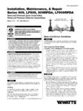
6 Bleed air at each test cock. When backflow preventer is filled, slowly open the downstream shutoff and fill the water supply system. This is nec-essary to avoid dislodging O-rings or causing damage to internal components. 10. Test: The 909 and LF909 Series backflow preventer must be tested by a certified tester at the time of installation in order to ascertain that the assembly is in full working order and may be relied upon to protect the safe drinking water as per applicable CheckRelief ValveSecond Check909QT/LF909 QTHow It OperatesThe unique relief valve construction incorporates two channels: one for air, one for water. When the relief valve opens, as in the accompanying air-in/water-out diagram, the right hand channel admits air to the top of the reduced pressure zone, relieving the zone vacuum.
7 The channel on the left then drains the zone to atmosphere. Therefore, if both check valves foul, and simultaneous negative supply and positive backpressure develops, the relief valve uses the air-in/water-out principle to stop potential Pressure ZoneWater OutAir In 2 Basic installation InstructionsWatts 3 4" 2" (20-50mm) 909QT/LF909QT High Capacity Relief Series: Location and installation ConsiderationsFor Repair kits and parts, refer to our Backflow Prevention Products Repair Kits & Service Parts price list PL-RP-BPD found on available, WattsBox Insulated Enclosures,for more information, send for ES-WB or WattsBoxMin. 12"ASSE approved for vertical installation 3 4" 2" flow up and down3 For indoor installations, it is important that the valve be easily accessible to facilitate testing and servicing.
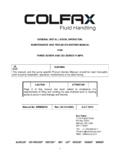
8 Series 909 and LF909 may be installed either vertically or hori-zontally. If it is located in a line close to wall, be sure the test cocks are easily accessible. A drain line and air gap should be piped from the relief valve connection as shown, where evidence of discharge will be clearly visible and so that water damage will not occur. Therefore, never install in concealed locations. NOTICETest cock must be located on the first or inlet shutoff Valve Below First Check ValveAir InWater OutMain 2" Air* GapFirst Check Valve909QT-S/LF909QT-SVertical installation - Upward Flow*For Air Gap information contact your technical sales representative or refer to ES-AG/ an area where freezing conditions do not occur, Series 909/LF909 can be installed outside of a building.
9 The most satisfactory installa-tion is above ground and should be installed in this manner when-ever an area where freezing conditions can occur, Series 909/LF909 should be installed above ground in an insulated enclosure. Series 909/LF909 may be installed in a vertical or horizontal line and in an accessible location to facilitate testing and servicing. A discharge line should be piped from the air gap at the relief valve connection making sure there is adequate drainage. Never pipe the discharge line directly into a drainage ditch, sewer or sump. Series 909 and Series LF909 should never be installed where any part of the unit could become submerged in standing water. Consideration should be given to the installation of external support structure as is generally recommended that backflow preventers never be placed in pits unless absolutely necessary, and then only, when approved by local codes.
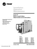
10 In such cases, a modified pit installation is or more smaller size valves can be piped in parallel (when approved) to serve a larger supply pipe main. This type of installation is employed where increased capacity is needed beyond that provid-ed by a single valve and permits testing or servicing of an individual valve without shutting down the complete number of valves used in parallel should be determined by the engineer s judgement based on the operating conditions of a specific IndoorsInstallation - Outside Building Above GroundInstallation - Parallel Consult Local Codes for Approval909QT-S/LF909S909QT-S/LF909QT-SA ir Gap(Drawings not to scale)TABLE OnE - CAPACITy REQuIRED FOR SySTEM50 gpm100 gpm150 gpm200 gpm250 gpm350 gpmTwo 3 4"Two 1"Two 11 4"Two 11 2"Two 11 2"Two 2"DevicesDevicesDevicesDevicesDevicesDev icesTable shows total capacity provided with dual valve installations of various sizes.