Transcription of RS601 THRU RS607 SINGLE-PHASE GLASS PASSIVATED …
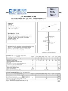
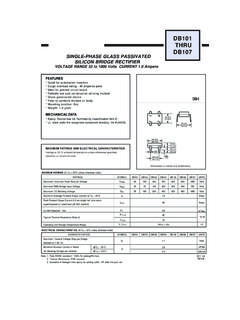
1 SINGLE-PHASE GLASS PASSIVATEDSILICON bridge RECTIFIERVOLTAGE RANGE 50 to 1000 Volts current AmperesMAXIMUM RATINGS AND ELECTRICAL CHARACTERISTICSR atings at 25oC ambient temperature unless otherwise or inductive RATINGS(@ TA=25OC unless otherwise noted)ELECTRICAL CHARACTERISTICS(@TA=25OC unless otherwise noted)Dimensions in inches and (millimeters)FEATURES* Silver-plated copper leads* Surge overload rating: 150 amperes peak* Low leakage* Low forward voltage * Mounting position: AnyMECHANICAL DATA* Epoxy:* UL listed the recognized component directory,file #94233 Device has UL flammability classification 94V-ORS-6 RATINGSM aximum Recurrent Peak Reverse VoltageMaximum RMS VoltageMaximum DC Blocking VoltageMaximum Average Forward Rectified Currentat TC=75oCPeak Forward Surge current ms single half sine-wavesuperimposed on rated load (JEDEC method)Typical Thermal Resistance (Note 1) current Squarad TimeSYMBOLVRRMVDCIFSMI2 TTJ, and Storage Temperature RangeR1 JCR1 JAIO-55 to + 150 Volts100RS601RS603RS605RS602RS604200800R S606501002008005070140560351000RS6071000 7004004002806006004202014-12 REV:ACHARACTERISTICSat Rated DC Blocking VoltageVFSYMBOLIRuAmpsMaximum DC Reverse CurrentMaximum Instantaneous Forward voltage at @TA= RS607 NOTES : Resistance : Heat-sink case mounted or if PCB "Fully ROHS compliant", "100% Sn plating (Pb-free)".
2 3. Measureed at 1 MHz and applied reverse voltage of ( ).280( ).180( ).220( ).048( ).052( ).740( ).780( ).895( ).935( )( x ).15 x . ( ).700( ) ( ).300( ).140( ) THRURATING AND CHARACTERISTICS CURVES ( RS601 THRU RS607 )INSTANTANEOUS FORWARD voltage , (V))URRENT, ( testper one diodeNUMBER OF F WARDORR(A),ENTRRCUEGSUnon-repetitiveTj=2 51 waveAAVER GRD CUARWOEF)RARENT, (CASE TEMPERATURE, (OC) waveR-loadon heatsinkPERCENT RATED PEAK REVERSE voltage , (%) REVERSE current , (M)ATA= 100 OCTA=25 OCMarking DescriptionR S 6 0 X V Y W W+-ACRectron Logo Part No. UL Logo Year code (Y:Last digit of year) Week code WW:01~52 voltage -code 1-------50V 5-------600V 2-------100V 6-------800V 3-------200V 7-------1000V 4-------400 VPACKAGING OF DIODE AND bridge RECTIFIERSBULK PACK PACKAGE RS-6EA PER BOXINNER BOX SIZE(mm)CARTON SIZE(mm)EA PER CARTONGROSSWEIGHT(Kg)200236*236*34497*25 5*1621, / CODE -B Rectron Inc reserves the right to make changes without notice to any product specification herein, to make corrections, modifications, enhancements or other changes.
3 Rectron Inc or anyone on its behalf assumes no responsibility or liabi- lity for any errors or inaccuracies. Data sheet specifications and its information contained are intended to provide a product description only. "Typical" paramet- ers which may be included on RECTRON data sheets and/ or specifications ca- n and do vary in different applications and actual performance may vary over ti- me. Rectron Inc does not assume any liability arising out of the application or use of any product or circuit. Rectron products are not designed, intended or authorized for use in medical, life-saving implant or other applications intended for life-sustaining or other rela- ted applications where a failure or malfunction of component or circuitry may di- rectly or indirectly cause injury or threaten a life without expressed written appr- oval of Rectron Inc.
4 Customers using or selling Rectron components for use in such applications do so at their own risk and shall agree to fully indemnify Rect- ron Inc and its subsidiaries harmless against all claims, damages and expendit- ures. DISCLAIMER NOTICE