Transcription of RTD Theory - Pyromation, Inc.
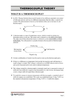
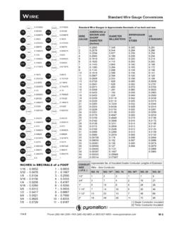
1 RTD Theory Page 1 So what exactly is an RTD? An RTD is a device which contains an electrical resistance source (referred to as a sensing element or bulb ) which changes resistance value depending on it s temperature. This change of resistance with temperature can be measured and used to determine the temperature of a process or of a material. RTD sensing elements come in two basic styles, wire wound and film. Wire wound elements contain a length of very small diameter wire (typically .0005 to .0015 inch diameter) which is either wound into a coil and packaged inside a ceramic mandrel, or wound around the outside of a ceramic housing and coated with an insulating material.
2 Larger lead wires (typically .008 to .015 inch diameter) are provided which allow the larger extension wires to be connected to the very small element wire. RTD Theory Page 2 Film type sensing elements are made from a metal coated substrate which has a resistance pattern cut into it. This pattern acts as a long, flat, skinny conductor, which provides the electrical resistance. Lead wires are bonded to the metal coated substrate and are held in place using a bead of epoxy or glass. Measuring Circuit: Besides the sensing element which we have previously discussed, the measuring circuit also consists of a combination of lead wires, connectors, terminal boards and measuring or control instrumentation.
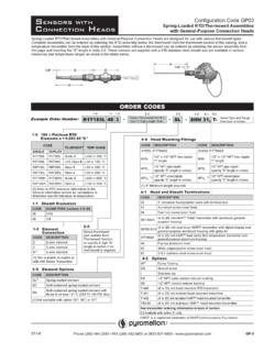
3 The exact make-up of the measurement circuit is dependent on many factors including: Temperature in the sensing area as well as the environmental conditions expected to exist between the sensor and instrumentation. Distance between the sensor and instrumentation. Type of interconnections the customer prefers. What type of wiring system is currently in place (if not new). RTD s are purchased with 2, 3 or 4 lead wires per element: RTD Theory Page 3 2-wire construction is the least accurate of the 3 types since there is no way of eliminating the lead wire resistance from the sensor measurement.
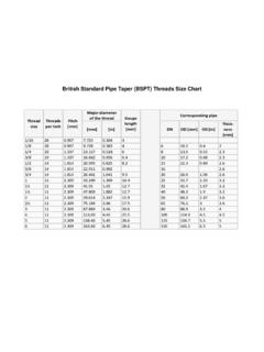
4 2-wire RTD s are mostly used with short lead wires or where close accuracy is not required. Measured resistance Rt = R1 + R2 + Rb 3-wire construction is most commonly used in industrial applications where the third wire provides a method for removing the average lead wire resistance from the sensor measurement. When long distances exist between the sensor and measurement/control instrument, significant savings can be made in using a three-wire cable instead of a four-wire cable. (R 1+2+R b ) - (R 2+3) = (R b ) The 3 wire circuit works by measuring the resistance between #1 & #2 (R 1+2) and subtracting the resistance between #2 & #3 (R 2+3) which leaves just the resistance of the RTD bulb (R b).
5 This method assumes that wires 1,2 & 3 are all the same resistance 4-wire construction is used primarily in the laboratory where close accuracy is required. In a 4 wire RTD the actual resistance of the lead wires can be determined and removed from the sensor measurement. The 4-wire circuit is a true 4-wire bridge, which works by using wires 1 & 4 to power the circuit and wires 2 & 3 to read. This true bridge method will compensate for any differences in lead wire resistances. RTD Theory Page 4 RTD RESISTANCE S Although RTD s are typically ordered as 100 Ohm Platinum sensors, other resistance s (200 Ohm, 500 Ohm, 1000 Ohm, etc.)
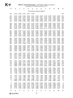
6 And materials (Nickel, Copper, Nickel Iron) can be specified. TEMPERATURE COEFFICIENT Temperature coefficient for RTD s is the ratio of the resistance change per 1 deg. change in temperature over a range of 0 - 100 deg. C. This ratio is dependent on the type and purity of the material used to manufacture the element. Most RTD s have a positive temperature coefficient which means the resistance increases with an increase in temperature. The temp. coeff. for pure platinum is .003926 ohm/ohm/deg. C. The normal coefficient for industrial RTD s is .00385 ohm/ohm/deg. C per the DIN std. 43760 -1980 & IEC 751 - 1983.
7 RTD TOLERANCES Accuracy or more properly, tolerance, for RTD s is stated at one point only, usually 0 deg. C. According to DIN 43760, there are 2 CLASSES of RTD s while ASTM E - 1137 recognizes 2 GRADES. DIN 43760 class B = .12% @ 0 C DIN 43760 class A = .06% @ 0 C ASTM E-1137 grade A = .05% @ 0 C ASTM E-1137 grade B = .10% @ 0 C SELF-HEATING Since RTD s are a resistor, they will produce heat when a current is passed through them. The normal current limit for industrial RTD s is 1 mA. Thin film RTD s are more susceptible to self-heating so 1 mA should not be exceeded. Wire wound RTD s can dissipate more heat so they can withstand more than 1 mA.
8 The larger the sheath or the more insulation there is the better chance there will be an error caused by self heating. RTD Theory Page 5 PYROMATION SUPPLIED RTD s Pyro uses all 3 styles of RTD elements previously discussed. The coiled wire wound is our standard. The platinum coils in these elements are secured to the inside of the bores with molten glass on one side only. The bores are then filled with alumina powder to support the windings and to keep them from shorting out. This construction allows for a strain free element, which allows them to be very accurate. This also makes for a fairly rugged element.
9 However, under severe vibration, these elements can drift or go open. The outer wound design seals the coils in molten glass which will keep the element wires from shorting out or breaking under severe vibration but will not allow them to expand or contract with temperature which puts strain on the wires. This strain causes the resistance to change and thus making them a less accurate style of construction. The thin film construction has the same setbacks as the outerwound elements plus they are not as accurate to begin with. Either the outerwound or the thin film would be good choices for high vibration areas.
10 ASTM E-1137 sets standards for manufacturing RTD s. Included in these specs are color codes, material requirements, pressure, shock, and vibration requirements, along with other properties. Pyro manufactures RTD s to some of these specs but we do not follow all of them. ASTM E-644 specifies test methods to verify the requirements stated in E-1137. RTD Theory Page 6 FOUR WIRE PRT s The most accurate lead wire configuration is the true 4-wire configuration. In a true 4-wire configuration, the resistance of the lead wires does not contribute to the resistance of the sensor. The true 4-wire measurement uses the current-potential method.