Transcription of RXV & 2Five HANDHELD DIAGNOSTICS & …
1 flight Systems industrial Products fsip . RXV & 2 Five HANDHELD DIAGNOSTICS . & troubleshooting guide . NORTH AMERICA: TECHNICAL ASSISTANCE & WARRANTY PHONE: 1-800-774-3946, FAX: 1-800-448-8124. SERVICE PARTS PHONE: 1-888-GET-EZGO (1-888-438-3946), FAX: 1-800-752-6175. INTERNATIONAL: SALES PHONE: 001-706-798-4311, FAX: 001-706-771-4609. E-Z-GO, A Textron Company, 1451 Marvin Griffin Road, Augusta, Georgia USA 30906-3852. 614804. 1-800-333-1194 flight Systems industrial Products fsip . RXV & 2 FIVE troubleshooting AND DIAGNOSTICS . TABLE OF CONTENTS. SECTION TITLE PAGE NO. HAND HELD DIAGNOSTICS . HOW TO USE THE RXV & 2 FIVE HAND HELD DIAGNOSTIC UNIT .. 1. MENUS .. 2. DIAGNOSTICS Report .. 2. Battery Functions .. 2. Pedal Functions .. 2. Motor and Heat Sink Functions.
2 3. Input 4. Output functions .. 4. Brake Functions .. 4. DIAGNOSTICS Report (real-time) .. 4. Battery Functions .. 4. Pedal Functions .. 5. Motor and Heat Sink Functions .. 5. Input 6. Output functions .. 7. Brake Functions .. 7. Battery and Warrant (read 8. 8. History .. 9. Error Messages .. 9. Warning Messages .. 10. Setting Top Speed and Performance Profiles .. 10. Course Energy Consumption .. 10. DIGITAL VOLT OHM METER .. 12. 12. ACCESSORY HARNESS .. 13. POWER SUPPLY .. 13. ERROR AND WARNING TABLE .. 13. RXV ERROR AND WARNING 14 - 20. 2 FIVE ERROR AND WARNING TABLE .. 21 - 26. troubleshooting & DIAGNOSTICS Owner's guide 1-800-333-1194 flight Systems industrial Products fsip . DIAGNOSTICS AND troubleshooting guide . HOW TO USE THE HAND HELD The E-Z-GO logo will display when the unit is first pow- ered up, then the menu title is displayed on the first line DIAGNOSTIC UNIT of the display screen with the menu selections indented under it.)
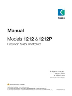
3 The E-Z-GO Hand Held Diagnostic Unit, P/N 614400 is used for troubleshooting , tuning, programming and the The vertical bar along the left side of the display screen retrieval of warranty information on the 48V RXV vehicle moves up and down when buttons 1 or 5 are pressed. and the 2 Five (LSV) vehicle. The length of the bar also changes depending on how many items are in a menu. When the bar is positioned at the top arrow the beginning of the menu has been reached; if the bar has reached the arrow at the bottom of the screen there are no more menu choices avail- DISPLAY SCREEN MENU TITLE HIGHLIGHTED MENU ITEM. BAR RXV OR LSV C*.*. DIAG REPORT. DIAG REALTIME. CONTROL BUTTONS. BATTERY/WARRANTY. ARROW ERRORS. WARNINGS. SETUP PERFORMANCE. POWER CORD To access the different diagnostic functions, use the five control buttons to scroll through the menus.
4 Buttons 1 and 5 will move the cursor up and down through the menu, button 4 will show the sub menu for the highlighted item. Button 2 will return to the top level menu. Button 3 is used as 'enter' or 'return'; hold the button for 3 With the vehicle key switch in the 'OFF' position, the hand held diagnostic unit is connected to the vehicle by plugging the power cord connector into the receptacle (CAN) located under the vehicle cup holder. Turn the key switch on to power up the hand held. If the hand held shows 'no connection' or a blank screen, check the cord and the CAN connections and wiring. For the 2 Five vehicle, when the hand held is powered up, you must toggle the 'rabbit/turtle' switch 5 times within 8 seconds to over ride the speedometer. If this is not done, incorrect readings will occur.
5 When the hand held unit is powered up, it will recognize which vehicle type it is connected to and give only those specific readings for that vehicle. The hand held unit has the ability to detect an older software version and pro- vides the user the ability to download the compatible new software. DIAGNOSTICS & troubleshooting guide Page - 1. 1-800-333-1194 flight Systems industrial Products fsip . DIAGNOSTICS AND troubleshooting guide . MENUS PEDAL FUNCTIONS ( 4 - 7). 4. THROTTLE SENSOR VOLTAGE: displayed as The Hand Held Diagnostic Unit, when connected to the 'THROTVOLT', the next line displays the sensor volt- vehicle, will provide access to information on the follow- age as 'LOW', 'NORMAL' or 'HIGH'. ing: DIAG REPORT. DIAGNOSTIC REPORT THROT VOLT. NORMAL. BATTERY FUNCTIONS (1 - 3) THROTTLE SW.
6 NORMAL. BRAKE VOLT. 1. BATTERY VOLTAGE: displayed as 'VOLTAGE', the NORMAL. next line displays 'HIGH','LOW' or the actual voltage in tenths of a volt. 5. THROTTLE SWITCH POSITION: displayed as 'THROTTLESW', the next line displays the switch volt- DIAG REPORT age as 'NORMAL' or 'ABNORMAL'. VOLTAGE. V DIAG REPORT. CURRENT THROT VOLT. A NORMAL. SOC THROTTLE SW. NORMAL NORMAL. BRAKE VOLT. NORMAL. 2. CALCULATED BATTERY CURRENT: displayed as 'CURRENT', the next line displays calculated current as 'HIGH', 'LOW' or the actual number in DC Amps. 6. BRAKE SENSOR VOLTAGE: displayed as 'BRAKE- VOLT', the next line displays the sensor voltage as 'LOW', 'NORMAL' or 'HIGH'. DIAG REPORT. VOLTAGE. V DIAG REPORT. CURRENT THROT VOLT. A NORMAL. SOC THROTTLE SW. NORMAL NORMAL. BRAKE VOLT.
7 NORMAL. 3. STATE OF CHARGE: displayed as 'SOC', the next 7. BRAKE SWITCH POSITION: displayed as 'BRAKE. line displays the state of charge for the battery pack as SW' the next line displays the switch voltage as 'NOR- 'HIGH', 'NORMAL' or 'LOW BATT'. MAL' or 'ABNORMAL'. DIAG REPORT RXV SCREEN ONLY. VOLTAGE DIAG REPORT. V THROTTLE SW. CURRENT NORMAL. A BRAKE VOLT. SOC NORMAL. NORMAL BRAKE SW. NORMAL. Page - 2 DIAGNOSTICS & troubleshooting guide 1-800-333-1194 flight Systems industrial Products fsip . DIAGNOSTICS AND troubleshooting guide . MOTOR & HEAT SINK FUNCTIONS (8 - 15) 12. MOTOR CURRENT: displayed as 'AC CURRENT', the next line displays the AC current in Amps. 8. MOTOR COMMAND SPEED: displayed as 'CMD- SPEED', the next line displays the speed in RPMs (revolutions per minute) that is being requested of the DIAG REPORT.
8 Motor by the pedal position. VEH SPEED. 24 MPH. AC CURRENT. DIAG REPORT A. CMD SPEED MOTORTEMP. 3544 RPM 17C. ACT SPEED. 3540 RPM. SPEEDSENSOR 13. MOTOR TEMPERATURE: displayed as 'MOTOR- NORMAL. TEMP', the next line displays the internal motor tem- perature in C. 9. MOTOR ACTUAL SPEED: displayed as 'ACTSPEED', the next line displays the actual motor speed in RPMs. DIAG REPORT. VEH SPEED. 24 MPH. DIAG REPORT ACCURRENT. CMD SPEED A. 3544 RPM MOTORTEMP. ACT SPEED 17C. 3540 RPM. SPEEDSENSOR. NORMAL 14. CONTROLLER HEAT SINK TEMPERATURE: dis- played as 'HEAT SINK TEMP', the next line displays the temperature in C. 10. MOTOR SPEED SENSOR displayed as 'SPEED. SENSOR', displays the status of the speed sensor. For troubleshooting see errors and warning chart. DIAG REPORT.
9 HEAT SINK TEMP. DIAG REPORT 25 C. CMD SPEED FAN. 3544 RPM ON. ACT SPEED FWDSWITCH. 3540 RPM ON. SPEED SENSOR. NORMAL 15. FAN function is displayed as "FAN", the next line dis- plays whether or not the controller cooling fan is on or 11. MOTOR VEHICLE SPEED displayed as 'VEH- off. SPEED', gives warning for a speed sensor error. 2 FIVE SCREEN ONLY. DIAG REPORT DIAG REPORT. VEH SPEED HEATSINKTEMP. 24 MPH 25 C. AC CURRENT FAN. A ON. MOTORTEMP FWD SWITCH. 17 C ON. DIAGNOSTICS & troubleshooting guide Page - 3. 1-800-333-1194 flight Systems industrial Products fsip . DIAGNOSTICS AND troubleshooting guide . INPUT FUNCTIONS (16 - 18) 20. SOLENOID: displayed as 'SOLENOID', the next line displays the solenoid state as 'ON' or 'OFF. 16. FORWARD SWITCH: displayed as 'FWD SWITCH', the next line displays the switch position as 'ON' or 'OFF'.
10 DIAG REPORT. BUZZER. DIAG REPORT OFF. FWD SWITCH SOLENOID. ON ON. REV SWITCH EBRAKE CUR. OFF A. RUN TOW SW. RUN. BRAKE FUNCTIONS (21). 17. REVERSE SWITCH: displayed as 'REV SWITCH', the next line displays the switch position as 'ON' or 'OFF'. 21. ELECTRIC BRAKE CURRENT: displayed as 'EBRAKECURR', the next line displays the brake cur- DIAG REPORT rent as a three place decimal in Amps; the brake cur- FWD SWITCH rent displayed below is 3 milliAmps. ON. REV SWITCH. OFF DIAG REPORT. RUN TOW SW BUZZER. RUN OFF. SOLENOID. ON. 18. RUN TOW SWITCH POSITION: displayed as 'RUN EBRAKE CUR. TOW SW', the next line displays the position of the A. run/tow switch as 'RUN' or 'TOW'. DIAG REPORT Press button #2 to get back to main screen FWD SWITCH. ON. REV SWITCH. OFF. RUN TOW SW DIAGNOSTICS REPORT (real - time read RUN only).