Transcription of SARA-S200 - U-blox
1 SARA-S200 . Size and power optimized RPMA module for the Machine Network . System Integration manual Abstract This document describes the features and the integration of the U-blox SARA-S200 Random Phase Multiple Access (RPMA) cellular module. The U-blox SARA-S200 module is an RPMA module in the LGA form factor and with the industry standard 4-wire Serial Peripheral Interface (SPI), allowing for easy integration with various host processors. Operating in the unlicensed GHz ISM band, the RPMA network features demonstrated up to 176 dB of link budget for superior connectivity. The module delivers unprecedented range, capacity, robustness and low power consumption, even in the most demanding of environments. UBX-17048649 - R01. SARA-S200 - System Integration manual Document Information Title SARA-S200 . Size and power optimized RPMA module Subtitle for the Machine Network . Document type System Integration manual Document number UBX-17048649.
2 Revision and date R01 24-Oct-2017. Disclosure restriction This document applies to the following products: Name Type number Firmware version PCN reference SARA-S200 SARA-S200 -00B-00 UBX-17053305. U-blox reserves all rights to this document and the information contained herein. Products, names, logos and designs described herein may in whole or in part be subject to intellectual property rights. Reproduction, use, modification or disclosure to third parties of this document or any part thereof without the express permission of U-blox is strictly prohibited. The information contained herein is provided as is and U-blox assumes no liability for the use of the information. No warranty, either express or implied, is given, including but not limited, with respect to the accuracy, correctness, reliability and fitness for a particular purpose of the information. This document may be revised by U-blox at any time.
3 For most recent documents, visit Copyright 2017, U-blox AG. U-blox is a registered trademark of U-blox Holding AG in the EU and other countries. ARM is the registered trademark of ARM Limited in the EU and other countries. UBX-17048649 - R01. Page 2 of 61. SARA-S200 - System Integration manual Preface U-blox technical Documentation As part of our commitment to customer support, U-blox maintains an extensive volume of technical documentation for our products. In addition to our product-specific technical data sheets, the following manuals are available to assist U-blox customers in product design and development. System Integration manual : This manual provides hardware design instructions and information on how to set up production and final product tests. Application Note: Provides general design instructions and information that applies to all U-blox cellular modules. See Section Related documents for a list of Application Notes related to your cellular module.
4 How to use this manual The SARA-S200 System Integration manual provides the necessary information to successfully design in and configure these U-blox cellular modules. This manual has a modular structure. It is not necessary to read it from the beginning to the end. The following symbols are used to highlight important information within the manual : An index finger points out key information pertaining to module integration and performance. A warning symbol indicates actions that could negatively impact or damage the module. Questions If you have any questions about U-blox cellular integration, please: Read this manual carefully. Contact our information service on the homepage Read the questions and answers on our FAQ database on the homepage technical Support Worldwide Web Our website ( ) is a rich pool of information. Product information, technical documents and helpful FAQ can be accessed 24h a day.
5 By E-mail Contact the nearest technical Support office by email. To ensure that your request is processed as soon as possible, use our service pool email addresses rather than any personal email address of our staff. You will find the contact details at the end of the document. Helpful Information when Contacting technical Support When contacting technical Support please have the following information ready: Module type ( SARA-S200 ) and firmware version Module configuration Clear description of your question or the problem A short description of the application Your complete contact details UBX-17048649 - R01 Preface Page 3 of 61. SARA-S200 - System Integration manual Contents Preface .. 3. 4. 1 System description .. 7. Overview .. 7. 7. 7. Pin description .. 8. Power states and supply interface .. 9. VCC_3V3 .. 10. VCC_VBATT .. 10. Operating states .. 11. Power-Off state.
6 11. Deep sleep state .. 11. Oscillator calibration state .. 11. Idle state .. 12. RX 12. TX state .. 12. System power .. 13. Application for power modes .. 14. Powered operating mode .. 14. Battery operated 14. Sleep mode assumptions .. 15. Active mode .. 15. SPI interface and sequences .. 16. SPI system interface overview .. 16. SPI mode and timing .. 17. Host initialization .. 17. Start-up (Power On) sequence .. 18. Wake sequence .. 19. Wake sequence (Synchronous) .. 19. Wake sequence (Asynchronous) .. 20. Host-Driven reset sequence .. 21. Host MRQ release / SARA-S200 allowed to sleep sequence .. 21. SPI messaging protocol .. 22. 22. Message protocol .. 23. Host Interface SPI bus state machine .. 25. SPI bus timing 26. Host message SPI 27. UBX-17048649 - R01 Contents Page 4 of 61. SARA-S200 - System Integration manual Host message Connect SPI example .. 29. RF connection.
7 31. RF diversity .. 31. Example antenna circuit .. 32. RF interference and channels to 32. PWR_ON .. 33. TOUT .. 33. RF _RHDN .. 33. RF_TXENA .. 33. Reserved pins (RSVD) .. 33. Features .. 34. Low Power mode .. 34. Over the Air update .. 34. 2 Design-In .. 35. Supply interfaces .. 35. Guidelines for VCC supply circuit design in Powered Mode .. 36. Guidelines for input supply circuit design using a switching regulator in Battery mode .. 37. Guidelines for VCC supply layout design .. 39. Guidelines for grounding layout design .. 39. System function interfaces .. 40. PWR_ON .. 40. SPI serial interface .. 40. Indicator signals .. 40. RF_SHDN .. 40. RF_TXENA .. 40. Design-in checklist .. 41. Schematic checklist .. 41. Layout checklist .. 41. Antenna checklist .. 41. Design guidelines .. 42. Layout guidelines per pin function .. 42. Host antenna trace design .. 42. Controlled RF impedance trace design.
8 43. Module placement .. 44. PCB land pattern and keep-outs .. 45. Module footprint and paste mask .. 46. Antenna design considerations .. 47. Diversity antenna considerations .. 48. Antennas used for SARA-S200 certification .. 48. Antenna termination .. 48. Antenna radiation .. 49. ESD immunity test precautions .. 50. 3 Handling and soldering .. 51. UBX-17048649 - R01 Contents Page 5 of 61. SARA-S200 - System Integration manual Packaging, shipping, storage and moisture preconditioning .. 51. Soldering .. 51. Soldering paste .. 51. Reflow soldering .. 51. Optical inspection .. 52. 52. Repeated reflow soldering .. 53. Wave soldering .. 53. Hand soldering .. 53. Conformal coating .. 53. 53. Grounding metal covers .. 53. Use of ultrasonic processes .. 53. 4 Approvals .. 54. FCC warnings .. 55. ISED warnings .. 56. ETSI warnings .. 56. Usage .. 57. Product labels .. 57. RF exposure statement.
9 57. WEEE directive .. 57. REACH directive .. 57. RoHS directive .. 57. Export compliance .. 57. Appendix .. 58. A Glossary .. 58. Related documents .. 60. Revision history .. 60. Contact .. 61. UBX-17048649 - R01 Contents Page 6 of 61. SARA-S200 - System Integration manual 1 System description Overview The U-blox SARA-S200 module is a cost effective solution intended for data throughput applications such as remote sensing that may require up to 100 kB per day. It features ultra-low power consumption mode for battery powered devices, and is suitable for applications that demand 10 years or longer field life on a single cell. The module's ultra-low -133 dBm Rx sensitivity permits cell sites to range typically between 50 and 200 sq miles. RPMA air interface characteristics RPMA Terrestrial Radio Access Time Division Duplex (TDD) operating mode Single-band support: ISM Band Proprietary RPMA Direct spread spectrum (DSSS).
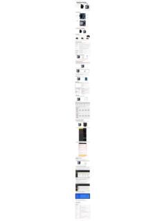
10 Table 1: RPMA Air Interface characteristics SARA-S200 is strictly a data module for embedded solutions. The 7-wire SPI supports handshaking for deep sleep modes. Along with the module, there are host common libraries provided to enable easy adoption to existing host application processors. The SARA-S200 antenna interface is provided via 50 antenna pads with a main RF port and a diversity RF port to further provide improved RF performance. Architecture SARA-S200 . VCC_3V3. VCC_VBATT. 8 Mbit Balun Airoha PA Memory PWR_ON. TX GHz RF. SPI. transceiver Filter ANT1 DPDT. WAKE. RF SW LNA Ingenu TOUT. PHY Baseband ANT2 RX RF_SHDN. Filter (BB) RF_TXENA. AFE ARM7. 26 MHz 32-bit TCXO. 78 MHz VCC_VBATT. to VCC_3V3 32 kHz JTAG. OSC. V VBack V FET. REG REG REG Switch To To BB To BB to Radio, Oscillators State Machine Core CPU I/Os Figure 1: SARA-S200 block diagram UBX-17048649 - R01 System description Page 7 of 61.