Transcription of Save these instructions for future ... - …
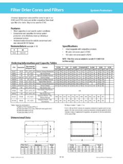
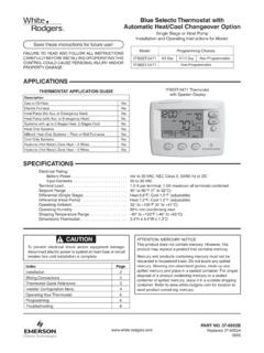
1 Blue Universal Thermostatwith Automatic Heat/CoolChangeover OptionModelProgramming Choices1F95-06717 Day5/1/1 DayNon-ProgrammablePART NO. 37-6979 BReplaces 37-6979A1345 Single Stage, Multi-Stage, Heat PumpInstallation and Operating instructions for Model: APPLICATIONSTHERMOSTAT APPLICATION GUIDE1F95-0671 Universal Thermostat SPECIFICATIONSTo prevent electrical shock and/or equipment damage, disconnect electric power to system at main fuse or circuit breaker box until installation is !Save these instructions for future use!FAILURE TO READ AND FOLLOW ALL instructions CAREFULLY BEFORE INSTALLING OR OPERATING THIS CONTROL COULD CAUSE PERSONAL INJURY AND/OR PROPERTY Pump (No Aux. or Emergency Heat)Ye sHeat Pump (with Aux. or Emergency Heat)Ye sSystems with up to 4 Stages Heat, 2 Stages CoolYe sHeat Only SystemsYe sMillivolt Heat Only Systems Floor or Wall FurnacesYe sCool Only SystemsYe sGas or Oil HeatYe sElectric FurnaceYe sHydronic (Hot Water) Zone Heat 2 WiresYe sHydronic (Hot Water) Zone Heat 3 WiresYe sWired Remote Temperature Sensor (Indoor or Outdoor)Ye sDual Fuel Feature (Heat Pump Mode, Outdoor Remote Required)Ye sATTENTION: MERCURY NOTICEThis product does not contain mercury.
2 However, this prod-uct may replace a product that contains and products containing mercury must not be discarded in household trash. Do not touch any spilled mercury. Wearing non-absorbent gloves, clean up any spilled mercury and place in a sealed container. For proper disposal of a product containing mercury or a sealed container of spilled mercury, place it in a suitable shipping container. Refer to for loca-tion to send product containing Diagrams3 Thermostat Quick Reference5 Installer Configuration Menu6 Operating Your Thermostat9 Programming10 Troubleshooting14 Electrical Rating: Battery mV to 30 VAC, NEC Class II, 50/60 Hz or DC Input-Hardwire .. 20 to 30 VACT erminal Load .. per terminal, maximum all terminals combinedSetpoint Range .. 45 to 99 F (7 to 32 C)Differential (Single Stage) .. Heat F; Cool FDifferential (Multi-Stage) .. Heat F; Cool FDifferential (Heat Pump).
3 Heat F; Cool FOperating 32 F to +105 F (0 to +41 C)Operating Humidity .. 90% non-condensing Temperature Range .. -40 to +150 F (-40 to +65 C)Dimensions "H x "W x " Old ThermostatBefore removing wires from old thermostat, mark wires for terminal identification so the proper connections will be made to the new thermostat. Installing New Thermostat1. Pull the thermostat body off the thermostat base. Forcing or prying on the thermostat will cause damage to the Place base over hole in wall and mark mounting hole locations on wall using base as a Move base out of the way. Drill mounting holes. If you are using existing mounting holes and the holes drilled are too large and do not allow you to tighten base snugly, use plastic screw anchors to secure the Fasten base snugly to wall using mounting holes shown in Figure 1 and two mounting screws.
4 Leveling is for appearance only and will not affect thermostat Connect wires to terminal block on base using appropriate wiring Push excess wire into wall and plug hole with a fire resistant material (such as fiberglass insulation) to prevent drafts from affecting thermostat Carefully line the thermostat up with the base and snap into Location2 "AA" alkaline batteries are included in the thermostat at the factory with a battery tag to prevent power drainage. Remove the battery tag to engage the replace batteries, set system to OFF, remove thermostat from wall and install the batteries in the rear along the top of the thermostat (see Figure 1). For best results, use a premium brand "AA" alkaline battery such as Duracell or Energizer . If the home is going to be unoccupied for an extended period (over 3 months) and is displayed, the batteries should be replaced before !
5 Thermostat installation and all components of the control system shall conform to Class II circuits per the NEC Figure 1 1F95-0671 Rear view of thermostat2 "AA" BatteriesPower Stealing Switches* A1 For Damper Control Not Applicable To This Model.*MountingHoleMountingHolePlace Levelacross Mounting Tabs(for appearance only)Place Levelacross Mounting Tabs(for appearance only)Thermostat Power MethodSwitch Position/DescriptionBattery Powered, no 24 Volt system power "On", thermostat runs on with Battery Back-up, for 24 Volt systems with common connection from transformer to "C" terminal on "On", thermostat runs on power directly from transformer with battery back-up.*Battery Powered with Power Stealing Assist, for 24 Volt systems with no common connection from transformer to "C" terminal on "On", thermostat runs on batteries and supplemental power drawn through the heat or cool circuit.
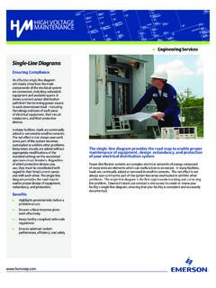
6 *Power Stealing Assist is very reliable to increase battery life, but on a small number of heating or cooling systems with high impedance electronic modules you may observe one of the following conditions:1. The furnace draft inducer motor may run with no call for The furnace fan may turn on with no call for heat or may not turn The furnace may not turn off when the call for heat The air conditioner may not turn off when the call for cool the Power Stealing Assist method is not compatible with your system, place the Power Stealing Switches to "Off". This cancels Power Stealing Assist, operates the thermostat on batteries and corrects the Stealing SwitchThe Power Stealing Switches (Figure 1, rear view) should be left in the "On" position for most systems. The information in the following table details the thermostat power method and switch Base3 WIRING DIAGRAMSF igure 2 Single Stage or Multi-Stage System (No Heat Pump) with Single TransformerSingleStage 1(SS1)Multi-Stage 2(MS2)OEnergized ConstantlyinCool ModeBEnergized Constantlyin Heat, Off,EmergencyModeNoOutputCoolMode2ndStag eCool Mode1st StageBlower/CirculatorFan Energizedon Call forCool (andHeat ifconfiguredfor ElectricHeat)No OutputHeat Mode2nd StageHeatMode1st StageOptional*24 Volt(Com-mon)24 Volt(Hot)CoolSystemYGW/ECLRCCLASS IITRANSFORMERHOT24 VACNEUTRAL120 VAC24 Volt(Hot)HeatRHY2W2 JumperDiagnosticIndicator InputorSystemMalfunctionSwitch InputComfort Alert II Module or Similar SystemDiagnostic ModuleSee Module Instructionsfor detailsO/B* Common connection required for diagnostic or malfunction 3 Single Stage or Multi-Stage System (No Heat Pump)
7 With Two TransformersSingleStage 1(SS1)Multi-Stage 2(MS2)NoOutputCoolMode2ndStageCool Mode1st StageBlower/CirculatorFan Energizedon Call forCool (andHeat ifconfiguredfor ElectricHeat)No OutputHeat Mode2nd StageHeatMode1st StageOptional 24 Volt(Com-mon)DiagnosticIndicator(Optiona l)24 Volt(Hot)CoolSystemYGW/ECLRCCLASS IITRANSFORMERHOT24 VACNEUTRAL120 VAC24 Volt(Hot)HeatRH120 VACR emove Jumper Wirebetween RH & RCHOT24 VACNEUTRALCLASS IITRANSFORMERHEATINGCOOLINGY2W2 JumperO/BOEnergized ConstantlyinCool ModeBEnergized Constantlyin Heat, Off,EmergencyModeSingle Stage and Multi-Stage ConnectionsRefer to equipment manufacturers' instructions for specific system wiring thermostat is designed to operate a single-transformer or two-transformer can configure the thermostat for use with the following systems: Single Stage (SS 1) gas, oil or (MS 2) gas, oil or wiring, see INSTALLER CONFIGURATION section for proper thermostat to equipment manufacturers' instructions for specific system wiring information.
8 After wiring, see CONFIGURA-TION section for proper thermostat diagrams shown are for typical systems and describe the thermostat terminal DESIGNATION DESCRIPTIONS Terminal Designation Description O/B ..Changeover valve for heat pump energized constantly in cooling and off/heating Y2 ..2nd Stage Compressor Y ..Compressor Relay G ..Fan Relay RC ..Power for Cooling RH ..Power for Heating C ..Common wire from secondary side of cooling (Optional). Required for fault indication, continuous back- light operation or remote temperature sensor operation 6 Powered closed 3rd wire for 3-wire zone valve W/E ..Heat Relay/Emergency Heat Relay (Stage 1) (3rd Stage Heat in HP2) W2 ..2nd Stage Heat (4th Stage Heat in HP2) - ..Common (DC) for wired remote temperature sensor S.
9 Frequency signal from remote temperature sensor + ..Power (DC) to remote temperature sensor L ..Compressor diagnostic indicator for systems with diagnostic connection typically found on Heat pump systems or with Copeland's Comfort Alert4 Single Stage3-wireZone ValveapplicationBlower/CirculatorFan EnergizedOpensValve(4)Constant24 Volt(Com-mon)24 Volt(Hot)CoolSystem6 YWCRCCLASS IITRANSFORMERHOT24 VACNEUTRAL120 VAC24 Volt(Hot)Heat(5)RHGJ umperClosesValve(6)Figure 5 3-Wire (SPDT) Heat Only Zone Valve WiringFigure 4 Heat Pump SystemsHeat Pump 1(HP1)Heat Pump 2(HP2)OEnergized inCool ModeBEnergized inHeat, Off,EmergencyModeNoOutput2ndStage(Com-pr essor)Heat andCool Mode1st Stage(Compressor)Blower/Circulator FanEnergized onCall for Heator Elect/GasOption forEmergencymodeHeat Mode - 3rdStage, Emergency Mode - 2nd StageHeat Mode-4thStage.
10 EmergencyMode - 2nd StageHeat Mode - 2ndStage, EmergencyMode - 1st StageHeat Mode - 3rd Stage, EmergencyMode - 1st StageOptional*24 Volt(Com-mon)Diagnostic Indicator or SystemMalfunctionSwitch24 Volt(Hot)CoolSystemY+W/ECLRCCLASS IITRANSFORMERHOT24 VACNEUTRAL120 VAC24 Volt(Hot)HeatRHJumperY2+W2 GComfort Alert II Moduleor Similar SystemDiagnostic ModuleSee Module Instructionsfor detailsO/B+Note: Dual Fuel option de-energizes Heat mode stage 1 (compressor) when auxiliary heat is energized+Note: Dual Fuel option de-energizes Heat mode stage 1 (compressor) when auxiliary heat is energized+Note: Dual Fuel option de-energizes Heat mode stage 1 (compressor) when auxiliary heat is energized+Note: Dual Fuel option de-energizes Heat mode stage 1 (compressor) when auxiliary heat is energizedWIRING DIAGRAMS Heat Pump ConnectionsRefer to equipment manufacturers' instructions for specific system wiring thermostat is designed to operate a single-transformer or two-transformer can configure the thermostat for use with the following systems: Heat PuMP tYPe 1 (HP 1).