Transcription of Screw pumps - IMO
1 This instruction is valid for all standard low pressure pumps : LPD, ACD, ACE, LPE, ACG/UCG, ACF/UCF, LPQ and ABQC ontents Page Pump identification 2 Installation 3 Start-up 8 Trouble shooting 10 !Before commencing any work, read this instruction carefully! Failure to comply with these instructions may cause damage and personal injury! Screw pumpsLow pressure pumpsInstallation and Start-up InstructionLP GB2LP instructions are valid for all low pressure pumps as specified in the Pump identification chart identificationABQLPQACF/UCFACG/UCGACELPE ACDLPD0150200250250320380450520600700800 90100110125100110125140160 NLNDKNKLNLNPBLN16 374515 IINNININIVVTVTVTRVRBBBBFBFYYPPEPEOPPOPA1 01A101A327A020A385A020A084A087A101A328 PJQ025032038 DKLNDKLN 3 NVTBA101 PINRTPump nameRotor lead (1)Shaft- seal design (1)Mounting (2)Valve (3)Also valid for optionCommentsPumpunit without shaft couplingO = max 5 bar(1) See Product description or Service instruction for specified pump model(2) B = Flange mounting F = Foot mounting Y = Vertical foot mounting(3)
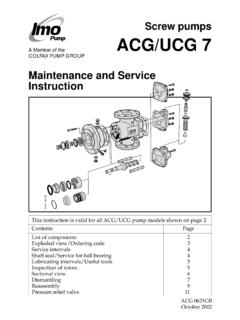
2 E = Without valve G = Valve with external return O = Valve with internal return for reduced pressure range P = Valve with internal return for total pressure rangeOptionA020 Pump with surface treated casing(s)A084 Pump with lifetime greased ball bearingA087 Pump with CCW-rotation and lifetime greased ballbearingA101 Pump with CCW-rotation, when not standardA327 Pump with Tuning A328 Pump with Tuning A385 A101 + A327 Material pump-body (1)Size (1)O = max 10 barDesign modificationPumpunit without shaft GBFig. 2 Lifting of pumpmax 90 min 60 max 90 min 60 ! Failure to comply with these instructions may cause damage and personal injury!Transport and storageAlways protect the pump against ingress of water and other impurities. Store the pump in a clean, dry and warm environment. The pump is delivered with the internals oiled and with protective covers over the pipe connections and drain openings.
3 These covers should remain in place for as long as possible during the mounting and installation procedure but must be removed before start up. ! All work carried out on the pump has to be performed in such a manner that risks for personal injury are observed! Lifting of pump ! All pumps should be lifted with straps securely attached to the pump or pump unit, so that the center of gravity is located between the straps in order to avoid tipping of the two eye bolts (M 20) securely fastened to the front cover for pumps LPQ and ABQ. Pump and connecting frame are lifted together using two eye bolts securely fastened to the top of the connecting frame. (Thread dimension is M 16, except for frame size 600, where it is M 20).Identification of safety instructionsNon compliance of safety instructionsidentified by the following symbol -could affect safety for instructions whereelectrical safety is involved,are identified by:Safety instructions which shall be considered forreasons of safe operation of the pump or pumpunit and/or protection of the pump or pump unititself are marked by the sign:ATTENTIONmax 90 min 60 Fig.
4 1 Clean and dry COMMENCING ANY WORK, READ THIS INSTRUCTION CAREFULLY!Design limitations and technical data for each pump are found in the Product description. Installation of IMO AB low pressure pumps does not require special skills. However, these instructions presume that the work is carried out by experienced fitters. Maintenance and service instructions, which are specific for each pump are presented in a separate of the complete pump unit with the lifting device attached to the motor, should be avoided as the motor s lifting provisions may not be able to carry the combined weight of the pump and motor. ! Lifting a complete pump unit, using slings or hooks attached to the pump or connecting frame may be dangerous since the centre of gravity of the pump unit may be higher than the points of pump must be securely mounted on a firm stable foundation and positioned so that it is easily accessible for inspection and for collecting oil spillage when servicing the pump should be considered.
5 ATTENTION The installation must always be designed to minimise damage. Should an operational or functional failure occur. precautions should be considered to collect oil spillage due to a broken pipe or pump housing, to stop pump operation if overheating should occur or if the oil volume is below a minimum tank and shaft couplingsThe pump shall be connected to its driver via a flexible shaft coupling. pumps of type ACG/UCG and ACF/UCF may also be driven via gears or pulleys as specified in the Product Description, provided the radial forces are kept within the specified range. An angular misalignment of corresponds to approx. mm deviation/100 coupling and alignment shall be selected not to transmit any axial or radial loads on the shaft ends. IMO AB standard couplings shall have a distance between the coupling halves as per table, fig 4. the coupling halves shall be secured by lock other types of couplings, please refer to respective maker s manual.
6 ! When fitting the shaft coupling, do not use a hammer or similar as this may damage the ball bearing and shaft seal. Use some kind of press tool. ! When handling liquids that may harm skin use gloves and/or protective clothing. ! When handling liquids which may involve fire hazards appropriate precautions to avoid danger are to be 4. Distance between coupling halves. (IMO AB standard coupling) Outer diameter Distance between Outer diameter Distance between of coupling coupling halves of coupling coupling halves (D mm) (t mm) (D mm) (t mm) A B A B 50 26 8 148 67 40 16 168 82 55 18 194 97 65 20 214 112 80 24 240 128 95 26 Fig. 3 Alignment of the IMO AB standard couplingtD4 max mmD6 max mmE4 max DSee table belowAn angular misalignment of corresponds to approx.
7 Mm deviation/100 alignmentDistance between coupling halvesCircularrun-outAXYx = y - t GBFig. 8 Deaeration ! Measures shall be provided to avoid accidental contact with the rotating shaft coupling. Any installed coupling guard shall permit easy access to the pump shaft for maintenance and inspection of the pump bearing and seal connectionsThe pipe work shall be installed and supported so that no pipe stresses are transfered to the pump pipe work should be tight in order to avoid leakage and infiltration of foreign particles and/or off valves should be installed in both suction and discharge pipes, so that the pump can be hydraulically lineThe suction pipe should be designed so that the total pressure drop, measured at the pump inlet flange, does not exceed the suction capability of the a proper calculation of the suction line including components such as valves, strainer, pipe bends etc.
8 Generally, the pressure drop in the suction line should be as low as possible, which is achieved if the suction pipe is short, straight and has a suitable velocity in the suction line should be kept in the range - m/s. For circulating systems, we recommend to keep it as low as suction line must be equipped with a port that allows filling the pump before lineThe discharge line should be dimensioned to keep the velocity in the range 1 - 3 installations with negative suction head, where the pump might be started against a pressurized system, a deaeration pipe with an orifice (2-3 mm recom mended) has to be installed. The deaeration pipe should be connected to the outlet pipe s highest point. This must also be installed when the pump is used as an stand-by Suction lineFig. 6 Pipe connections For direct driven pumps the alignment between pump and motor shafts must be kept within the following limits: Max run-out Max angular misalignment (mm) (degrees) Type LPD and ACD (n/a short coupled) Other types 5.
9 6LP 11 Liquid trapFig. 9 StrainerStrainerThe pump has to be protected from foreign matter, such as weld slag, pipe scale, etc., that could enter the pump via the suction line. If the cleanliness of the system cannot be guaranteed, a strainer must be installed in the inlet pipe near the pump. For practical reasons a suction strainer with mm mesh openings is recommended:The size of the strainer should be selected so that it is large enough to allow adequate pressure at the pump inlet. The pressure drop across the strainer should preferably not exceed bar at max. flow rate and normal operating viscosity. A vacuum gauge between the strainer and the pump inlet is recommended to indicate when the strainer needs : The service life of the pump is decisively influenced by the degree of contamination of the fluid being conveyed, that means, by the number, size and hardness of the abrasive seal drainThe pump should be installed so that any leakage from the shaft seal does not become a hazard.
10 As the shaft seal has to be lubricated a small amount of oil dripping cannot be avoided. Provisions to collect the leakage from the shaft seal must be made. A drain pipe can be connected to the drain connection on the pump, (not applicable to pump series LPD). However, when pumping heavy fuel oil or any other liquid that is likely to become very viscous at ambient temperature, we recommend that the liquid is allowed to drop freely from the drain trapIn some mounting arrangements the pump may not retain the liquid at stand still. In such installations the suction pipe should be arranged so it forms a liquid trap together with the pump, keeping the pump half filled with liquid. See fig. 10 Shaft seal GBbarFig. 12 GaugesGaugesGauges for monitoring the pump s working conditions are recommended. These gauges should be placed readable as close to the pump s in- and outlet flanges as possible.