Transcription of Screw Thread Design - Fastenal
1 Rev. 3-4-09 Screw Thread Design Screw Thread Fundamentals A Screw Thread is defined as a ridge of uniform section in the form of a helix on either the external or internal surface of a cylinder. Internal threads refer to those on nuts and tapped holes, while external threads are those on bolts, studs, or screws. The Thread form is the configuration of the Thread in an axial plane; or more simply, it is the profile of the Thread , composed of the crest, root, and flanks. At the top of the threads are the crests, at the bottom the roots, and joining them are the flanks. The triangle formed when the Thread profile is extended to a point at both crests and roots, is the fundamental triangle. The height of the fundamental triangle is the distance, radially measured, between sharp crest and sharp root diameters. The distance measured parallel to the Thread axis, between corresponding points on adjacent threads, is the Thread pitch.
2 Unified Screw threads are designated in threads per inch. This is the number of complete threads occurring in one inch of threaded length. Metric Thread pitch is designated as the distance between threads (pitch) in millimeters. On an internal Thread , the minor diameter occurs at the crests and the major diameter occurs at the roots. On an external Thread , the major diameter is at the Thread crests, and the minor diameter is at the Thread roots. The flank angle is the angle between a flank and the perpendicular Thread axis. Flank angles are sometimes termed half-angle of the Thread , but this is only true when neighboring flanks have identical angles; that is, the threads are symmetrical. Unified Screw threads have a 30 flank angle and are symmetrical. This is why they are commonly referred to as 60 degree threads. Pitch diameter is the diameter of a theoretical cylinder that passes through the threads in such a way that the distance between the Thread crests and Thread roots is equal.
3 In an ideal product, these widths would each equal one-half of the Thread pitch. Threads Per Inch Thread Pitch Rev. 3-4-09 An intentional clearance is created between mating threads when the nut and bolt are manufactured. This clearance is known as the allowance. Having an allowance ensures that when the threads are manufactured there will be a positive space between them. For fasteners, the allowance is generally applied to the external Thread . Tolerances are specified amounts by which dimensions are permitted to vary for convenience of manufacturing. The tolerance is the difference between the maximum and minimum permitted limits. Thread Fit Thread fit is a combination of allowances and tolerances and a measure of tightness or looseness between them. A clearance fit is one that provides a free running assembly and an interference fit is one that has a positive interference thus requiring tools for the initial run-down of the nut.
4 For Unified inch Screw threads there are six standard classes of fit: 1B, 2B, and 3B for internal threads; and 1A, 2A, and 3A for external threads. All are considered clearance fits. That is, they assemble without interference. The higher the class number, the tighter the fit. The A designates an external Thread , and B designates an internal Thread . Classes 1A and 1B are considered an extremely loose tolerance Thread fit. This class is suited for quick and easy assembly and disassembly. Outside of low-carbon threaded rod or machine screws, this Thread fit is rarely specified. Classes 2A and 2B offer optimum Thread fit that balances fastener performance, manufacturing, economy, and convenience. Nearly 90% of all commercial and industrial fasteners use this class of Thread fit. Classes 3A and 3B are suited for close tolerance fasteners. These fasteners are intended for service where safety is a critical Design consideration.
5 This class of fit has restrictive tolerances and no allowance. Socket products generally have a 3A Thread fit. The following illustration demonstrates the pitch diameter allowances on a -10 bolt and nut. The axial distance through which the fully formed threads of both the nut and bolt are in contact is called the length of Thread engagement. The depth of Thread engagement is the distance the threads overlap in a radial direction. The length of Thread engagement is one of the key strength aspects and one of the few which the designer may be able to control. Rev. 3-4-09 Per the acceptance requirements of ASME , System 21, the allowance specified for the Class 2A external threads is used to accommodate the plating thickness. The plain finished parts (or plated parts prior to plating) would be tested for adherence to these tolerances with a 2A Go/No-Go Thread gauge. The 2A Go gauge would ensure the pitch diameter falls below the maximum requirement; the No-Go gauge would verify that the pitch diameter is above the minimum requirement.
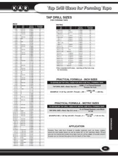
6 A standard electro-zinc plated 2A part would be gauged with the Class 3A Go (due to the plating metal thickness) and 2A No-Go gauge after plating. Thread damages such as dents, scrapes, nicks, or gouges and plating build-up are not cause for rejections unless they impair function and usability. Threads that do not freely accept the appropriate Go ring gauge shall be inspected by allowing the screwing of the gauge with maximum allowable torque value of: Torque = 145 x d3 (for inch series), where Torque is in-lbs. and d is diameter in inches- IFI 166 Torque = x d3 (for metric series), where Torque is Nm and d is diameter in mm- IFI 566 Thread Series There are three standard Thread series in the Unified Screw Thread system that are highly important for fasteners: UNC (coarse), UNF (fine), and 8-UN (8 Thread ). A chart listing the standards sizes and Thread pitches with their respective Thread stress areas is listed in the Fastenal Technical Reference Guide, along with a special series designated UNS.
7 Below are some of the aspects of fine and coarse threads. Go and No-Go Gauges are threaded rings that are tapped in such a way that they ensure proper tolerancing of parts. Similar devices are available for internally threaded fasteners. Minor Thread nicking on external threads may still be found acceptable. Rev. 3-4-09 Fine Thread Since they have larger stress areas the bolts are stronger in tension Their larger minor diameters develop higher torsional and transverse shear strengths They can tap better in thin-walled members With their smaller helix angle, they permit closer adjustment accuracy Coarse Thread Stripping strengths are greater for the same length of engagement Improved fatigue resistance Less likely to cross Thread Quicker assembly and disassembly Tap better in brittle materials Larger Thread allowances allow for thicker platings and coatings Numerous arguments have been made for using either fine or coarse threads; however, with the increase in automated assembly processes, bias towards the coarse Thread series has developed.
8 UNR Threads The UNR Thread is a modified version of a standard UN Thread . The single difference is a mandatory root radius with limits of to times the Thread pitch. When first introduced decades ago, it was necessary to specify UNR (rounded root) threads. Today, all fasteners that are roll threaded should have a UNR Thread because Thread rolling dies with rounded crests are now the standard method for manufacturing most threads. UNJ Threads UNJ Thread is a Thread form having root radius limits of to times the Thread pitch. With these enlarged radii, minor diameters of external Thread increase and intrude beyond the basic profile of the UN and UNR Thread forms. Consequently, to offset the possibility of interference between mating threads, the minor diameters of the UNJ internal threads had to be increased. 3A/3B Thread tolerances are the standard for UNJ threads. UNJ threads are now the standard for aerospace fasteners and have some usage in highly specialized industrial applications.
9 UNJ bolts are like UNR, but the curve of the Thread root is gentler which requires that it be shallower. In fact, the Thread root is so shallow that the bolt Thread cannot mate with a UN nut, so there is a UNJ nut specification as well. Thread ProductionThread ProductionThread ProductionThread Production Threads can be produced by either cutting or rolling operations. The shank of a blank designed for cut threading will be full-size from the fillet under the head to the end of the bolt. Producing cut Rev. 3-4-09 threads involves removing the material from a bolt blank with a cutting die or lathe in order to produce the Thread . This interrupts the grain flow of the material . Rolled threads are formed by rolling the reduced diameter (approximately equal to the pitch diameter) portion of the shank between two reciprocating serrated dies. The dies apply pressure, compressing the minor diameter ( Thread roots) and forcing that material up to form the major diameter ( Thread crests).
10 Imagine squeezing a balloon with your hand; you compress with your fingers to form the valley, while allowing part of the balloon to expand between your fingers. This is the concept behind roll threading. Rolled threads have several advantages: more accurate and uniform Thread dimension, smoother Thread surface, and generally greater Thread strength (particularly fatigue and shear strength). Thread cutting requires the least amount of tooling costs. It is generally only used for large diameter or non-standard externally threaded fasteners. Thread cutting is still the most commonly used method for internal threads. Thread Strength Two fundamentals must be considered when designing a threaded connection. 1. Ensure that the threaded fasteners were manufactured to a current ASTM, ANSI, DIN, ISO or other recognized standard. 2. Ensure that the Design promotes bolts to break in tension prior to the female and/or male threads stripping.