Transcription of SD-13-4863 Bendix ABS / ATC Controllers (Standard ...
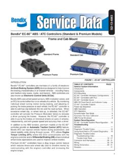
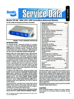
1 SD-13-4863 . Bendix EC-60 ABS / ATC Controllers (Standard & Premium Models). Frame and Cab Mount Standard Frame Standard Cab Premium Frame Premium Cab FIGURE 1 - EC-60 Controllers . INTRODUCTION. TABLE OF CONTENTS PAGE. Bendix EC-60 Controllers are members of a family of electronic General System Information Antilock Braking System (ABS) devices designed to help improve Introduction.. 1. the braking characteristics of air braked vehicles - including heavy Components .. 2. and medium duty buses, trucks, and tractors. ABS Controllers are ECU Mounting .. 2. also known as Electronic Control Units (ECUs). EC-60 controller Hardware Configurations .. 2. EC-60 Controllers with PLC .. 3. Bendix ABS uses wheel speed sensors, ABS modulator valves, and EC-60 controller Inputs .. 3. an ECU to control either four or six wheels of a vehicle. By monitoring ABS Off-Road Switch and Indicator Lamp .. 4. individual wheel turning motion during braking, and adjusting or EC-60 controller Outputs.
2 4. pulsing the brake pressure at each wheel, the EC-60 controller is Power-Up Sequence .. 5. able to optimize slip between the tire and the road surface. When ABS Operation .. 6. excessive wheel slip, or wheel lock-up, is detected, the EC-60 ATC Operation .. 7. controller will activate the Pressure Modulator Valves to simulate Dynamometer Test Mode .. 8. a driver pumping the brakes. However, the EC-60 controller is Automatic Tire Size Calibration .. 8. ABS Partial Shutdown .. 9. able to pump the brakes on individual wheels (or pairs of wheels), System Reconfiguration independently, and with greater speed and accuracy than a driver. EC-60 controller System Reconfiguration .. 10. In addition to the ABS function, premium models of the EC-60 Troubleshooting controller provide an Automatic Traction Control (ATC) feature. General.. 11. Bendix ATC can improve vehicle traction during acceleration, and Diagnostic Trouble Codes.
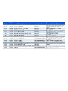
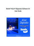
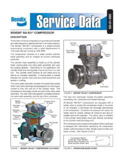
3 12. lateral stability while driving through curves. ATC utilizes Engine Using Hand-Held or PC-based Diagnostics .. 13. Diagnostic Trouble Codes: Torque Limiting (ETL) where the ECU communicates with the Troubleshooting Index .. 16. engine's controller and/or Differential Braking (DB) where individual Trouble Code Tests .. 18 - 27. wheel brake applications are used to improve vehicle traction. Connector and Harnesses .. 28 - 31. Premium EC-60 Controllers have a drag torque control feature Wiring .. 32 - 34. which reduces driven-axle wheel slip (due to driveline inertia) by Wiring Schematics .. 28 - 31. Glossary .. 41. communicating with the engine's controller and increasing the engine torque. 1. Sensor Clamping 90 Speed Sleeve Sensors Straight Speed Sensors FIGURE 2 - Bendix WS-24 WHEEL SPEED SENSORS FIGURE 4 - POWER LINE WITHOUT PLC SIGNAL. Delivery (Port 2). Supply (Port 1). Electrical Connector M-32 . M-32QR Modulator Modulator Exhaust (Port 3).
4 FIGURE 3 - M-32 AND M-32QR MODULATORS FIGURE 5 - POWER LINE WITH PLC SIGNAL. COMPONENTS ECU MOUNTING.. The EC-60 controller 's ABS function utilizes the following Cab ECUs components: Cab-mounted EC-60 Controllers are not protected against Bendix WS-24 wheel speed sensors (4 or 6, moisture, and must be mounted in an environmentally depending on ECU model and configuration). Each protected area. sensor is installed with a Bendix Sensor Clamping Sleeve All wire harness connectors must be properly seated. The . Bendix M-32 or M-32QR Pressure Modulator use of secondary locks is strongly recommended. Valves (4, 5, or 6 depending on ECU model and CAUTION: All unused ECU connectors must be covered configuration) and receive any necessary protection from moisture, etc. Dash-mounted tractor ABS Indicator Lamp Cab ECUs utilize connectors from the AMP MCP Service brake relay valve product family. Dash-mounted trailer ABS Indicator Lamp (used on all towing vehicles manufactured after March 1, Frame ECUs 2001) Frame-mounted EC-60 Controllers may be mounted on Optional blink code activation switch the vehicle frame, but only in locations where they will not be subjected to direct tire spray.
5 ECU mounting bolts must Optional ABS off-road switch. (Off-road feature is not be torqued to to 9 Nm. available on all models - See Chart 1.). CAUTION: The frame wire harness connectors must be The EC-60 controller ATC function utilizes the following properly seated with the seals intact (undamaged). All additional components: unused connector terminals must be plugged with the Traction control valve (may be integral to the service appropriate sealing plugs. Failure to properly seat or brake relay valve or a stand-alone device) seal the connectors could result in moisture or corrosion Dash-mounted ATC status/indicator lamp damage to the connector terminals. ECUs damaged by J1939 serial communication to engine control module moisture and/or corrosion are not covered under the Bendix Stop lamp switch input (may be provided using the warranty. ECU hardware input or J1939) Frame ECUs utilize Deutsch connectors. Optional ATC off-road switch 2.
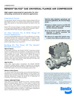
6 ECU Mounting Input Sensors PMVs ATC Blink Serial Communication PLC ABS ATC Retarder Model Voltage Codes J1587 J1939 Off-Road Off-Road Relay Standard Cab 12 4 4. Frame Standard Cab 12 4 4. PLC Frame Premium Cab 12 4/6 4/5/6. Frame Premium Cab 24 4/6 4/5/6. HARDWARE CONFIGURATIONS CHART 1 - EC-60 Controllers AVAILABLE. Standard Models Alternatively, the part number shown on the ECU label Standard model EC-60 Controllers support four sensor/ can be identified as a PLC or non-PLC model by calling four modulator (4S/4M) applications. Certain models the Bendix TechTeam at 1-800-AIR-BRAKE (1-800-247- support Power Line Carrier (PLC) communications, with 2725). all models supporting 12 volt installations. See Chart 1. for more details. EC-60 controller INPUTS. Premium Models Battery and Ignition Inputs . Premium model EC-60 Controllers support applications The ECU operates at a nominal supply voltage of 12 or 24. up to six sensor/six modulator (6S/6M) installations with volts, depending on the model of the ECU.
7 The battery ATC and drag torque control. All 12 volt models support input is connected through a 30 amp fuse directly to the PLC. 24 volt models do not support PLC. See Chart 1 for battery. more details. The ignition input is applied by the ignition switch through a 5 amp fuse. EC-60 Controllers WITH PLC. Since March 1, 2001, all towing vehicles must have an Ground Input in-cab trailer ABS Indicator Lamp. Trailers transmit the The EC-60 controller supports one ground input. See status of the trailer ABS over the power line (the blue wire pages 35 to 40 for system schematics. of the J560 connector) to the tractor using a Power Line Carrier (PLC) signal. See Figures 4 and 5. Typically the ABS Indicator Lamp Ground Input (Cab ECUs signal is broadcast by the trailer ABS ECU. The application Only). of PLC technology for the heavy vehicle industry is known EC-60 cab ECUs require a second ground input (X1-12). as PLC4 Trucks.
8 The Standard PLC EC-60 controller for the ABS indicator lamp. The X1 wire harness connector and the Premium EC-60 controller (12 volt versions) contains an ABS indicator lamp interlock (X1-15), which support PLC communications in accordance with SAE shorts the ABS indicator lamp circuit (X1-18) to ground if J2497. the connector is removed from the ECU. Identifying an EC-60 controller with PLC Bendix WS-24 Wheel Speed Sensors Refer to the information panel on the ECU label to see if Wheel speed data is provided to the EC-60 controller from the controller provides PLC. the WS-24 wheel speed sensor (see Figure 2). Vehicles An oscilloscope can be used to measure or identify the have an exciter ring (or tone ring ) as part of the wheel presence of a PLC signal on the power line. The PLC assembly, and as the wheel turns, the teeth of the exciter signal is an amplitude and frequency modulated signal. ring pass the wheel speed sensor, generating an AC signal.
9 Depending on the filtering and load on the power line, The EC-60 controller receives the AC signal, which varies the PLC signal amplitude can range from mVp-p to in voltage and frequency as the wheel speed changes. Vp-p. Suggested oscilloscope settings are AC coupling, Vehicle axle configurations and ATC features determine 1 volt/div, 100 sec/div. The signal should be measured at the number of WS-24 wheel speed sensors that must the ignition power input of the EC-60 controller . be used. A vehicle with a single rear axle requires four Note: An ABS trailer equipped with PLC, or a PLC wheel speed sensors. Vehicles with two rear axles can diagnostic tool, must be connected to the vehicle in order utilize six wheel speed sensors for optimal ABS and ATC. to generate a PLC signal on the power line. performance. 3. Diagnostic Blink Code Switch ABS Indicator Lamp Control with Optional A momentary switch that grounds the ABS Indicator Lamp Diagnostic Blink Code Switch (Cab and Frame output is used to place the ECU into the diagnostic blink ECUs).
10 Code mode and is typically located on the vehicle's dash Cab and frame-mount EC-60 Controllers have internal panel. circuitry to control the ABS Indicator Lamp on the dash panel. ABS Off-Road Switch and Indicator Lamp The ABS Lamp Illuminates: Operation 1. During power up ( when the vehicle is started) and WARNING: The ABS off-road mode should not be used on turns off after the self test is completed, providing no normal, paved road surfaces because vehicle stability and Diagnostic Trouble Codes (DTCs) are present on the steerability may be affected. When the ECU is placed in tractor. the ABS off-road mode, the ABS Indicator Lamp will flash 2. If the ECU is unplugged or has no power. constantly to notify the vehicle operator that the off-road mode is active. 3. When the ECU is placed into the ABS off-road mode (the lamp flashes rapidly). Premium EC-60 Controllers use a dash-mounted switch 4. To display blink codes for diagnostic purposes after the to place the ECU into the ABS off-road mode.