Transcription of Section 2 Electrical Circuits - Automotive Training and ...
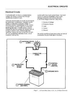
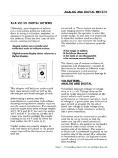
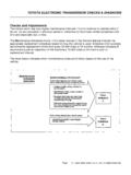
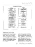
1 Electrical circuit Diagnosis - Course 6232-1A circuit is a complete path for current when voltage is applied. Thereare three basic types of Circuits : Series Parallel Series-parallelAll Circuits require the same basic components: Power source Protection device Conductors Load Control device GroundComponentsof a CircuitAll Circuits have thesebasic 2-01TL623f201 Section 2 Electrical CircuitsTypes of CircuitsSection 22-2 TOYOTA Technical TrainingPower source - In Automotive Circuits , the source is typically device - Circuits require protection from excessivecurrent. Excessive current generates heat and can damage wires,connectors, and components. Fuses, fusible links, and circuit breakersprotect Circuits by opening the circuit path when there is too - The load can be any component that uses electricity to do work: Light Coil MotorControl device - The simplest control device is a switch.
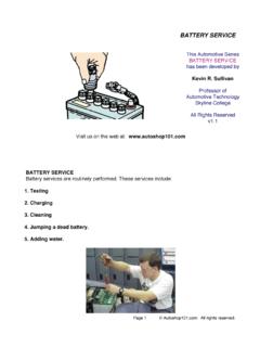
2 A switchopens or closes the path for current. Close the switch and current ispresent to operate the load. Open the switch and current stops. Theload no longer control device can do more than just turn the load on or off. It canalso regulate how the load works by varying the amount of current inthe circuit . A dimmer is an example of such a control are other types of control devices: Relays Transistors ECUsGround - The connection to ground provides a shortcut" back to thesource. Ground is typically any major metal part of a vehicle. You canthink of ground as a zero voltage reference. Ground provides a commonconnection that all Circuits can use so that they do not have to be wiredall the way back to the circuit type is determined by how the power source, protectiondevices, conductors, loads, control devices, and grounds are CircuitsElectrical circuit Diagnosis - Course 6232-3 Simple Series CircuitThis diagram shows a simple series voltage is applied through the fuseto the control device (switch).
3 When theswitch closes, there is current in a singlepath through the load (lamp) to 2-02TL623f202cA series circuit has these key features: Current is the same in every part of the circuit . The sum of all the individual resistances equals the total resistancein the circuit . The sum of the individual voltage drops in the circuit equals thesource series circuit has only one path for current. That means current isthe same through every part of the circuit . If any part of the circuit isbroken or disconnected, the whole circuit will stop working. No currentis present in a series circuit unless there is continuity through theentire FeaturesSeries CircuitsSection 22-4 TOYOTA Technical TrainingYou can use Ohm's Law to predict the behavior of electricity in a series Circuits , apply Ohm's Law as follows: Total circuit resistance (RT) equals the sum of the individual loadresistances (R1 + R2).
4 -RT = R1 + R2 circuit current (I) equals voltage (E) divided by total resistance (R).- I = E/R Voltage drop (ER1, ER2) across each load equals current (I) timesload resistance (R1, R2).-ER1 = I x R1-ER2 = I x R2In most modern texts, current is represented as I" and voltage as E."You may also see these represented as A" for amperage, instead of I"for current, and V" instead of E" for voltage. When using thatterminology, the Ohm's Law equation looks like this: A = s Law inSeries CircuitsWhen troubleshooting, use Ohm s Law topredict the behavior of a series 2-03TL623f203cApplying Ohm s LawNOTEE lectrical CircuitsElectrical circuit Diagnosis - Course 6232-5 Use Ohm's Law to troubleshoot series Circuits : Poor connections and faulty components can increase resistance. Since E/R = I, more resistance means less current. Less current affects the operation of the loads (dim lamps, slowrunning motors).
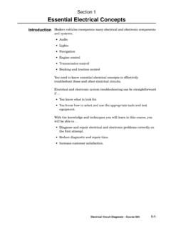
5 There is no current if there is a break (open circuit ) anywhere inthe current path. Since E/R = I, lower voltage also means less current and highervoltage means more current. High voltage increases current and can also affect circuit operation(blown fuses, premature component failure). Section 22-6 TOYOTA Technical TrainingVoltage Drops ina Series CircuitTroubleshoot bytaking voltagemeasurements with adigital 2-04TL623f204cVoltage drops in a series circuit - Every element in a circuit thathas resistance generates a voltage drop. The load in this circuit (lamp) generates the largest voltage drop. The dimmer generates a smaller, variable voltage drop to controlthe brightness of the lamp. Other components also generate even smaller voltage Fuse and fuse connectors- Wiring- Harness connectors The sum of all the voltage drops is equal to the source CircuitsElectrical circuit Diagnosis - Course 6232-7 Current in aSeries CircuitWhen practical, removethe fuse to measurecurrent in a 2-05TL623f205cCurrent in a series circuit - Current in a series circuit is the sameat every point in the circuit .
6 Measure current by opening the circuit and inserting the meter inseries. The circuit now includes the DMM in series with the circuit . Use a fused lead if removing the circuit 22-8 TOYOTA Technical TrainingMeasuring Resistance in aSeries CircuitRemove the fuse before beginningresistance measurements. To test thedimmer, disconnect it from the 2-06TL623f206cResistance in a series circuit - To make resistance measurements: Remove power from the circuit (turn it off or pull the circuit fuse). Isolate components to be tested from the rest of the circuit (disconnect or remove the component). Test suspect components one at a the series circuit above, isolate the dimmer for resistance testing. Resistance varies as the dimmer knob turns. Resistance is highest with the dimmer turned all the way to Dim." Resistance is lowest with the dimmer turned all the way to Bright.
7 "EXAMPLEE lectrical CircuitsElectrical circuit Diagnosis - Course 6232-9 Open CircuitThis open circuit betweenthe dimmer and the lampmeans the lamp doesnot operate at all (a breakin the current path).Fig. 2-07TL623f207 Open circuit - Any break (open) in the current path of a series circuitmakes the whole circuit inoperative. Open Circuits can be caused by: Broken or loose connections Cut wire Faulty componentSection 22-10 TOYOTA Technical TrainingFind an OpenCircuitLook for an open circuitby testing for voltage inthe circuit . Start with thepoint closest to thepower source (battery)and move toward thecircuit 2-08T623f208cTesting for available voltage - Find the fault in an open circuit bytesting for available voltage. Begin at the fuse. Work your way point by point toward the circuit ground. Proceed until you find a point where voltage is no longer present.
8 The open circuit is between your last two test CircuitsElectrical circuit Diagnosis - Course 6232-11 Split - HalfMethodCircuits with easy accessto components can usethe split-half method toisolate the 2-09TL623f209cSplit-Half Method - You can use the split-half method on circuitswhere access to the related components is good. The split-half methodworks as follows: Locate the middle area of the circuit that has the problem. Determine if the source (battery +) or ground side of that Section ofthe circuit is bad by the following:- Check for available voltage on the source Check for continuity to ground on the ground side. Split the bad Section you found in step 2 in half and repeat thesame tests. Continue splitting the circuit into smaller halves repeating steps 2and 3 until you isolate the cause of the 22-12 TOYOTA Technical TrainingContinuityCheck to Find anOpen CircuitLook for an open circuitby testing for a logical sequence,check individualsegments of the 2-10T623f210cTesting for continuity - The preferred method of testing a circuit iswith power applied and checking for voltage that is not possible, find the fault in an open circuit by testingfor continuity as follows: Remove power from the circuit (turn it off or pull the circuit fuse).
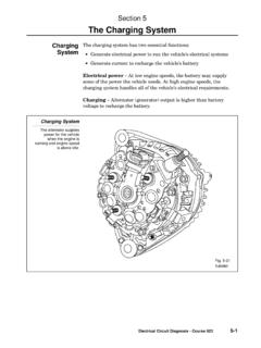
9 Refer to the wiring diagram to choose individual sections of thecircuit for continuity checks. Use a DMM to check each Section . Isolate components and sectionsas needed (by disconnecting or removing wires or components). Proceed until you find a Section that does not show continuity (veryhigh resistance). The open circuit will be in that CircuitsElectrical circuit Diagnosis - Course 6232-13 Short CircuitThe short circuit shownin this diagram is beforethe load. It provides anunwanted path forcurrent to flow to most cases, a shortlike this increases currentso much that it blows thecircuit 2-11TL623f211cShort circuit - A short circuit is a fault in the current path. A shortcan be: an unwanted path between two parts of a circuit . an unwanted path between part of a circuit and ground. an unwanted current path inside a component.
10 An unwanted path between two separate current - Short Circuits may cause excessive current. This typically blows the circuit fuse. It may not be possible to troubleshoot the circuit under a short circuit - To isolate a short circuit , disconnect sectionsor components of the circuit one at a time. Refer to the Electrical wiring diagram to determine a logicalsequence of testing. Use continuity checks to find and isolate unwanted current 22-14 TOYOTA Technical TrainingIsolating a Short CircuitYou can troubleshoot a short circuit withcontinuity checks, or you can use a sealedbeam headlight in the isolation methodshown 2-12TL623f212cIsolating a short circuit - circuit breakers and short detectors maydamage some Circuits . The following method works well for locatingmost short Circuits : Remove the related fuse. Jumper in a sealed beam headlight to the fuse connections (theheadlight becomes the load in the circuit allowing you to isolate thearea with the short).