Transcription of SECTION : 3 FRICTION BELT DRIVES - ERIKS
1 76"One-Shot" TensioningFenner belts are Precision Built to ensure inherent length stability and matching during storage and on the drive. Over many years, the principle of "one-shot" tensioning has been verified by successful DRIVES the world over. Install the belts to be a snug fit around the pulleys. Spin the pulleys 3-4 revolutions to bed belts into the pulley grooves.(Note: if done manually, beware of finger entrap-ment between belts and pulleys) Tension the belts to the setting forces from the table. Run the drive under load for 15-20 minutes. Stop the drive, check tension & reset to the basic value (standard V and wedge belts) if PLUS & Quattro PLUS belts should be reset to the a drive that is properly designed for the application there should be no need for further attention during the life of the short centre distance DRIVES where the deflection of the belt is too small to measure accurately it is recommended that both deflection and setting force be of belt tensioning using Fenner Belt Tension Indicator Calculate the deflection in mm on a basis of 16mm per metre of centre distance.
2 Centre distance (metres) x 16 = deflection (mm). Set the lower marker ring at the deflection distance required in mm on the lower scale. Set the upper marker ring against the bottom edge of the top tube. Place the belt tension indicator on top of the belt at the centre of span, and apply a force at right angles to the belt, deflecting it to the point where the lower marker ring is level with the top of an adjacent belt. Read off the setting force value indicated by the top edge of the upper marker ring. Compare this force to the kgf value shown in the table. If a Fenner Belt Tension Indicator is not available, a spring balance and rule will :For single belt DRIVES a straight edge should be placed across the two pulleys to act as a datum for measuring the amount of the measured force falls within the values given, the drive should be satisfactory.
3 A measured force below the basic value indicates new drive should be tensioned to the value to allow for the normal drop in tension during the running-in the drive has been running for 15 20 minutes, under load the tension should be checked and re-adjusted, if radial cracks on belt side and baseGenerally caused by slippage due to insufficient belt tension, but excessive heat and/or chemical fumes can also cause the same swelling or softeningCaused by excessive contamination by oil, certain cutting fluids, water or rubber during runningOften caused by incorrect tensioning, particularly on long centre DRIVES . If a slightly higher (or lower) tension does not cure the problem there may be a critical vibration frequency in the system which requires re-design or use of banded belts. Consult your local Authorised Distributor Technical groove wear can cause rapid belt failure.
4 Check grooves for wear with a Fenner groove TENSION INDICATOR APPLIESSETTING FORCE AT MID CENTRE DISTANCEBeltSectionSetting force to deflect belt16 mm per metre of spanSmall pulleydiameter (mm)Basic setting x setting forcesNewtons (N)kilograms (kgf)Newtons (N)kilograms (kgf)SPZXPZ & QXPZ56 to to to , XPA & QXPA80 to to to , XPB& QXPB112 to to to ,& QXPC224 to to & to 1005 to to (& HA banded)80 to 14010 to to to 20020 to to to 40040 to to to 60070 to to setting forces below are designed to cover a wide range of DRIVES . A precise setting force for individual applications can be calculated. Please consult your local Authorised Distributor or use the 'Fenner Select' design software at in mm(larger marker ring)Setting force in kgf(smaller marker ring)Fenner Wedge and Vee-Belt Tensioning InstructionsFRICTION BELT DRIVESSECTION : 316mm deflection per 1 metre of centre distanceBeltSectionSetting force to deflect belt16 mm per metre of spanSmall pulleydiameter (mm)Basic setting forcesNewtons (N)kilograms (kgf)USPB112 to to to to to ForcesFenner Belt Tension IndicatorSetting Forces Ultra PLUS 150 FEN01/14.
5 DRIVE DESIgN & MAINTENANCE MANUAL77 installation AND TAKE-UP ALLOWANCEBelt Pitch Length(mm) installation AllowancesTake-up(mm)SPZZSPAASPBBSPCC8VD 410 to 530205530 to 840253010850 to 116050151170 to 1500201510 to 1830251840 to 2170302180 to 283065402840 to 3500503520 to 4160604170 to 5140705220 to 6150856180 to 75001057600 to 85001258880 to 1017014510600 to 12500175within one third of the centre distance from the small tensioning pulley must have at least the same diameter as the small pulley of the pulley movemement must allow for passing the belts over the outside diameter of one of the drive pulleys on installation , and should also allow for belt stretch/bedding modern wedge belt drive is a highly efficient power transmission medium, but optimum performance will not be achieved without correct tension and installation -both shafts and pulleys are parallel and in LockAll Fenner V and wedge belt pulleys use Taper Lock shaft fixing.
6 Detailed instructions for fitting and dismounting Taper Lock products are included with Taper Lock comparatively old in principle today's belt drive is an extremely efficient method of transmitting power between prime mover and owes its present high performance standards to many years of research and development by engineers and technologists, leading to significant refinements in materials and derive maximum benefit from such advances it is important that the simple installation and operation procedures set out here are closely followed. Making these routines standard practice will ensure optimum performance and long, trouble-free life from Fenner belt DRIVES . installation PULLEYSB efore assembling the drive, check the pulley grooves are free from scores or sharp edges, and all dimensions conform to the relevant installation is straightforward with Taper Lock but follow all steps on the installation leaflet provided with every Taper Lock bush.
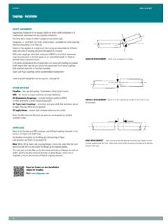
7 ALIgNMENTGood alignment of pulleys is important to avoid belt flank wear. The diagrams opposite show some of the common alignment faults. Pulley misalignment should not exceed 1/2 angular and 10mm / metre drive centre distance, laser alignment device is available, which facilitates quick, easy and accurate pulley alignment - consult your local Authorised Distributor. BELT INSTALLATIONWhen the pulleys have been correctly positioned on the shafts, the belts can be installed to complete the drive centre distance should be reduced prior to the installation of the belts so that they may be fitted without the use of force. Under no circumstances must belts be prised into the grooves. Belts and pulley grooves can easily be damaged by using sharp tools to stretch the belts over the pulley installation allowance given in the table opposite is the minimum recommended reduction in centre distance for the various belt sections and lengths to allow for correct take-up allowance given in the same table should be added on to the calculated centre distance to allow for belt stretch/bedding in.
8 GUARDSW here guards are necessary it is desirable to use mesh materials to permit adequate should be generously sized to allow for incidental belt flap. TENSIONINg PULLEYSIf tensioning (jockey) pulleys are to be used on wedge belt DRIVES , they must be grooved pulleys working on the inside of the drive, preferably on the slack side. The pulley should be positioned as close as possible to the large pulley. Flat tensioning pulleys, bearing on the outside of the drive are permissible only with V and not with wedge belts. They should be positioned SECTION : 3 FRICTION BELT DRIVESI nstallation and Operation of Wedge and Vee-Belt DrivesINSTALLATION AND TAKE-UP ALLOWANCEBelt Pitch Length(mm)Take-up(mm)USPBUSPC2180 to 28303050202840 to 3500253520 to 4160304170 to 5140355220 to 6150456180 to 7500557600 to 8500658880 to 101707510600 to 1250090 Ultra PLUS 150