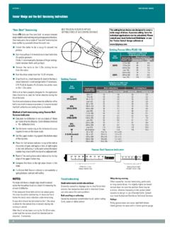
Transcription of SECTION : 5 DRIVE COUPLINGS - FPT Group
1 SECTION : 5 drive couplings COUPLINGS - installation SHAFT ALIGNMENT. Appropriate alignment of the coupled shafts (or driven shaft to flywheel) is a fundamental requirement for any coupling installation . The three basic modes of shaft misalignment are shown right. Composite more than one mode, misalignment is available for some COUPLINGS (detailed elsewhere in this Manual). Details of the degrees of misalignment that can be accommodated by different types and sizes of coupling are given throughout this manual. With some COUPLINGS , axial shaft orientation (DBSE) is not critical, whereupon coupling component orientation (given as an 'assembled length' or 'distance between faces') becomes crucial. ANGULAR MISALIGNMENT shafts are at an angle to one another It should be remembered that misalignment can cause extra loading on coupled shaft support bearings and can reduce the operational life of some COUPLINGS .
2 Best practical alignment is therefore desirable. Taper Lock Rigid COUPLINGS cannot accommodate misalignment. Laser alignment equipment can be supplied, see page 85. OTHER CRITERIA. Fenaflex tyre gap and seating. Tyre/element clamping bolt torque. HRC do not use to couple resiliently mounted machinery. All Elastomeric COUPLINGS consider ambient conditions (FRAS. PARALLEL MISALIGNMENT shafts are in line angularly and parallel to each other, but are or other alternative element material required?). off-set radially. All Taper Lock COUPLINGS remember bush grips shaft first and draws hub on to taper. This may affect axial alignment. All applications ensure shaft diameter tolerances are correct. Note: Fenaflex tyres and flywheel elements are accompanied by detailed installation data. TAPER LOCK. Most of the Fenaflex and HRC COUPLINGS , and all Rigid COUPLINGS featured in this SECTION use Taper Lock shaft fixing.
3 For detailed instructions on the fitting and dismounting of Taper Lock products see Shaft Fixings page 132. AXIAL MISALIGNMENT refers to errors in the axial spacing of coupling hubs/flanges, but also includes appplicational "end float" where shafts move axially increasing or decreasing the distance Note: When fitting Taper Lock coupling flanges it should be noted that the bush between shaft ends. grips the shaft initially and draws the flange up the tapered surface. This may have a small effect on the final axial positioning of flanges on machine shafts, and the resultant distance between coupling flanges, where this is important to the fit and function of flexible coupling elements. View the Fenner on-line installation videos for Fenaflex Visit: 124.
