Transcription of Section 5: System Arrangements - Schneider Electric
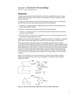
1 Section 5: System Arrangements Bill Brown, , Square D Engineering Services Introduction The selection of System arrangement has a profound impact upon the reliability and maintainability of the System . Several commonly-used System topologies are presented here, along with the pros and cons of each. The figures for each of these assume that the distribution and utilization voltage are the same, and that the service voltage differs from the distribution/utilization voltage. The symbology (low voltage circuit breaker, low voltage drawout circuit breaker, medium voltage switch, medium voltage breaker) reflects the most commonly-used equipment for each arrangement .
2 The symbology used throughout this Section is shown in figure 5-1: Figure 5-1: Symbology Radial System The radial System is the simplest System topology, and is shown in figure 5-2. It is the least expensive in terms of equipment first-cost. However, it is also the least reliable since it incorporates only one utility source and the loss of the utility source, transformer, or the service or distribution equipment will result in a loss of service. Further, the loads must be shut down in order to perform maintenance on the System . This arrangement is most commonly used where the need for low first-cost, simplicity, and space economy outweigh the need for enhanced reliability.
3 Typical equipment for this System arrangement is a single unit substation consisting of a fused primary switch, a transformer of sufficient size to supply the loads, and a low voltage switchboard. 1. Radial System with primary selectivity This arrangement is shown in figure 5-3. If two utility sources are available, it provides almost the same economic advantages of the radial System in figure 2 but also gives greater reliability since the failure of one utility source will not result in a loss of service (note that an outage will occur between the loss of the primary utility source and switching to the alternate source unless the utility allows paralleling of the two sources).
4 The loss of the transformer or of the service or distribution equipment would still result in a loss of service. Maintenance on the System requires all loads to be shut down. Figure 5-2: Radial System Figure 5-3: Radial System with Primary Selectivity An automatic transfer scheme may optionally be provided between the two primary switches to automatically switch from a failed utility source to an available source. Most often metal-clad circuit breakers are used, rather than metal-enclosed switches, if this is the case. More about typical equipment application guidelines follows in a subsequent Section of this guide.
5 2. Expanded radial System The radial systems shown in figures 5-2 and 5-3 can be expanded by the inclusion of additional transformers. Further, these transformers can be located close to the center of each group of loads to minimize voltage drop. Reliability increases with a larger number of substations since the loss of one transformer will not result in a loss of service for all of the loads. Figure 5-4 shows an expanded radial System utilizing multiple substations, but still with only one utility source and only one primary feeder: Figure 5-4: Expanded Radial System with one utility source and a single primary feeder A more reliable and maintainable arrangement utilizing multiple primary feeders is shown in figure 5-5.
6 In the System of figure 5-5, each unit substation is supplied by a dedicated feeder from the service entrance switchgear. Each substation is also equipped with a primary disconnect switch to allow isolation of each feeder on both ends for maintenance purposes. Typical service entrance equipment consists of a metal-clad switchgear main circuit breaker and metal-enclosed fused feeder switches. Metal-Clad circuit breakers may be used instead of metal-enclosed feeder switches if required. Figure 5-5: Expanded Radial System with one utility source and multiple primary feeders 3.
7 Figure 5-6 shows an expanded radial System utilizing multiple substations and two utility sources, again with metal-clad primary switchgear but with a duplex metal-enclosed switchgear for utility source selection: Figure 5-6: Expanded Radial System with two utility sources and multiple primary feeders Of the Arrangements discussed this far, the arrangement of figure 5-6 is the most reliable it does not depend upon a single utility source for System availability, nor does the failure of one transformer or feeder cause a loss of service to the entire facility.
8 However, the loss of a transformer or feeder will result in the loss of service to a part of the facility. More reliable System Arrangements are required if this is to be avoided. Loop System The loop System arrangement is one of several Arrangements that can allow one System component, such as a transformer or feeder cable, to fail without causing a loss of service to a part of the facility. Figure 5-7 shows a primary loop arrangement . The advantages of this arrangement over previously-mentioned Arrangements are that a failure of one feeder cable will not cause one part of the facility to experience a loss of service and that one feeder cable can be maintained without causing a loss of service (note that an outage to part of the System will be experienced after the failure of a feeder cable until the loop is switched to accommodate the loss of the cable).
9 In figure 5-7 metal-clad circuit breakers are used as the feeder protective devices. Fused metal-enclosed-feeder switches could be utilized for this, but caution must be used if this is considered since the feeder fuses would have to be able to serve both transformers and the feeder and transformer fuses would have to coordinate for maximum selectivity. It must be noted that the System arrangement of figure 5-7 is designed to be operated with the loop open, , one of the four loop switches shown would be normally-open. If closed-loop operation were required, metal-clad circuit breakers should be used instead to provide maximum selectivity (this arrangement is discussed further below).
10 Momentary paralleling to allow maintenance of one Section of the loop without causing an outage to one part of the facility can be accomplished with metal-enclosed loop switches, however, if caution is used in the System design and maintenance. 4. Figure 5-7: Primary Loop System Secondary-Selective System Another method of allowing the System to remain in service after the failure of one component is the secondary- selective System . Figure 5-8 shows such an arrangement . The System arrangement of figure 5-8 has the advantage of allowing one transformer to fail without causing a loss of service to one part of the plant.