Transcription of Section 5 Transfer Case - Testroete
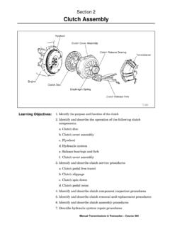
1 Manual Transmissions & Transaxles Course 3021. Identify the purpose and function of the Transfer Describe 4WD Describe AWD Describe Transfer case operationa. Gear drive Transfer caseb. Chain drive Transfer casec. Planetary gear type5. Identify and describe the operation of the following Transfer caseand transaxle components:a. Planetary gear unitb. Center differentialc. Shift mechanismd. Wait mechanism6. Identify and describe the operation of the differential lock7. Identify and describe the operation of the Automatic DisconnectingDifferential ( )8. Identify Transfer case lubricationa. Describe the trochoid pump used on some Transfer casesSection 5 Transfer CaseLearning Objectives:Component Testing2 toyota Technical TrainingA four wheel drive (4WD) vehicle has more pulling power and tractionsince it drives all four wheels.
2 To drive all four wheels, the powertrainrequires a drive axle at each end of the vehicle, a second propeller shaftand a Transfer case . The Transfer case is mounted to the rear of thetransmission and its purpose is to drive the additional shaft andprovide a gear reduction mode in four wheel drive torque is equally distributed to the front and rear axles and thevehicle is driven in a straight line, all wheels turn at the same speed,as do the two drive shafts. When the vehicle is driven in a turnhowever, all four wheels rotate at different speeds because each of thewheels has a different turning radius around the center of the outer front wheel turns the fastest, followed by the outer rear, theinner front and the inner rear the front axle is turning faster than the rear axle, the driveshafts also turn at different speeds.
3 This does not present a problemwhen the vehicle is driven on loose surfaces such as sand or snowbecause the tires will slip on the loose surface. However, when drivenon pavement, the difference in speeds causes tire scuffing and bind upof the powertrain. At low speeds the bind up may cause the engine tostall. Some Transfer case designs use a center differential to provideproportional distribution of torque to the axles eliminating the bind upeffect in the (AWD)Full-time 4WD or all-wheeldrive (AWD) Transfer casesinclude a center differentialbetween the front and reardrive shafts and maintainconstant power to both thefront and rear Transfer case design features increases your knowledgeof Transfer case operation and provides for more accurate 5 Transfer CaseIntroductionTRX ESP Troubleshooting GuideManual Transmissions & Transaxles Course 302 There are three types of Transfer case operating systems: part time,full time and multi mode.
4 In each of these systems high and low gearcan be part time four wheel drive system allows two wheel orfour wheel drive. When four wheel drive is selected, torque is evenlydistributed to the front and rear axles. Because the wheels turn atdifferent speeds as described earlier, part time four wheel drivevehicles should operate in two wheel drive on further contrast the three types of Transfer case designs it isimportant to understand the operating characteristics in 4WD whentraction is lost. In the part time system when one wheel loses traction,all the torque for that axle goes to the wheel with the least since the Transfer case distributes equal torque to each axle,the opposite axle has torque delivered to the a full time four wheel drive system or a multi modefour wheel drive system, if one wheel loses traction all torque goesto the wheel and axle with the least traction.
5 This is when you wouldlock the center differential causing the torque to be equally distributedto the front and rear axle similar to part time the event one wheel on each axles lost traction, the torque wouldstill go to the wheel with the least traction. What is needed at thispoint is a locking differential that causes both wheels at the rear axleto be driven Transfer case is attached to the rear of the transmission. It has asingle input shaft driven by the transmission output shaft and twooutput shafts, one for the front drive axle and one for the rear driveaxle. There are two designs that have been used in various Toyotamodels. The first was a gear design used in pickup models and4 Runners that were used until 1995. The land cruiser has used anexclusive gear design that is used in the current model.
6 The seconddesign with several variations is the silent chain model used in all rearwheel drive model pickups and land cruiser gear drive Transfer case has three majorcomponents: the input shaft assembly, the idler gear assembly and thecenter differential assembly. The input shaft assembly is driven by thetransmission output shaft and has a single drive gear. The idler gearassembly is driven by the input drive gear and provides for high andlow gear. The low speed idler gear is mounted to the idler gearassembly and rotates on a set of needle roller bearings. The high & lowclutch sleeve engages the low speed idler gear and the high speed idlergear for low CaseTypesTransfer CaseConstructionGear DriveTransfer CaseComponent Testing4 toyota Technical TrainingThe center differential assembly is driven either by the high speedidler gear or the low speed idler gear on the idler gear assembly.
7 Thehigh speed output gear rotates on the center differential front case andis driven by the high speed idler gear. It is coupled to the centerdifferential by the No. 1 high & low clutch sleeve. The low speed outputgear is attached to the center differential case and is driven by the lowspeed idler gear. The front drive clutch sleeve locks the centerdifferential by locking the front output shaft to the center differentialfront case . An oil pump, driven by the idler gear assembly, CruiserGear Drive Transfer CaseThe land cruiser uses a gear drive transfercase; the power flows in through the inputshaft and is transferred through gears toboth the front and rear drive ESP Troubleshooting GuideManual Transmissions & Transaxles Course 302 Shifting between high speed and low speed is done with a floormounted shift selector while the vehicle is stopped.
8 When the shiftselector is moved, the high & low clutch sleeve on the idler gearassembly and the No. 1 high & low clutch sleeve on the centerdifferential assembly move to the right at the same time. When lowspeed is selected, the low speed idler gear is engaged with the highspeed idler gear and the high speed output gear is disengaged from thecenter differential case . The high gear ratio ( :1) between thesmaller low speed idler gear and the larger low speed output gearprovides low high speed is selected, the high speed idler gear is disengagedwith the low speed idler gear and the high speed output gear isengaged with the center differential case . The gear ratio in high is 1:1as the input drive gear and high speed output gear have the samenumber of teeth.
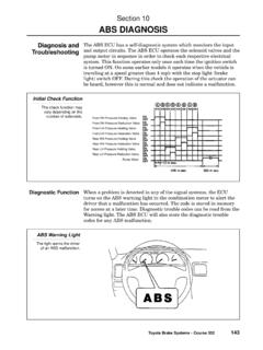
9 When the center differential case is driven, the pinionshaft transfers torque through the pinion gears to the side gears,driving the front and rear output DriveTransfer CaseOperationWhen low speed isselected, the low speedidler gear is engaged withthe high speed idler gearand the high speed outputgear is disengaged from thecenter differential electric shift actuator motor (discussed later in this Section ) causesthe front drive clutch sleeve to lock the front output shaft to the centerdifferential front case , completing the center differential lock actuator is controlled by a center differential lock switch located onthe instrument panel and a 4WD control Testing6 toyota Technical TrainingThe chain drive Transfer case has a similar function to the gear drivetransfer case .
10 This type of Transfer case uses a planetary gear setinstead of a countershaft to provide low range gear reduction. It alsouses a large silent chain instead of an idler gear to Transfer power tothe front output shaft. A synchronizer assembly allows changingranges from L4 to H4 without stopping. In 4WD, the front drive clutchsleeve connects the output shaft to the chain sprocket and chain, whichdrives the front output shaft. This Transfer case has its own oil pump toensure proper Drive Transfer CaseA chain drive Transfer case uses a largesilent chain to Transfer power from the rearoutput shaft to the lower front output DriveTransfer CaseTRX ESP Troubleshooting GuideManual Transmissions & Transaxles Course 302 The planetary gear unit is constructed in the following manner: The Transfer input shaft is splined to the planetary sun gear.