Transcription of EM15Y–01 INSTALLATION - Testroete
1 EM 66. ENGINE MECHANICAL cylinder HEAD. EM15Y 01. INSTALLATION . HINT: S Thoroughly clean all parts to be assembled. S Before installing the parts, apply fresh engine oil to all slid- ing and rotating surfaces. S Replace all gaskets and oil seals with new ones. 1. PLACE cylinder HEAD ON cylinder BLOCK. (a) Place a new cylinder head gasket on the cylinder block Lod No. surface with the Lod No. stamp upward. NOTICE: Be careful of the INSTALLATION direction. (b) Place the cylinder head quietly in order not to damage the gasket with the bottom part of the head.
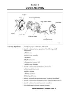
2 A01058. 2. INSTALL cylinder HEAD BOLTS. HINT: S The cylinder head bolts are tightened in 2 progressive 8 4 2 5 9 steps (steps (b) and (d)). S If any cylinder head bolt is broken or deformed, replace it. (a) Apply a light coat if engine oil on the threads and under 10 6 1 3 7 the heads of the cylinder head bolts. (b) Using a 10 mm bi hexagon wrench, install and uniformly tighten the 10 cylinder head bolts and plate washers, in several passes, in the sequence shown. Torque: 8 4 2 5 9. 1ZZ FE: 49 N m (500 kgf cm, 36 ft lbf). 2ZZ GE: 35 N m (375 kgf cm, 26 ft lbf).
3 If any one of the cylinder head bolts does not meet the torque specification, replace the cylinder head bolt . 10 6 1 3 7. A01057 A10369. (c) Mark the front of the cylinder head bolt with paint. (d) 1ZZ FE: 180 . 90 Retighten the cylinder head bolts 90 in the numerical or- Front der shown. (e) 2ZZ GE: Painted Mark Retighten the cylinder head bolts 180 in the numerical order shown. (f) 1ZZ FE: A12097 Check that the paint mark is not at a 90 angle to the front. 2000 CELICA (RM744U). EM 67. ENGINE MECHANICAL cylinder HEAD. (g) 2ZZ GE: Check that the paint mark is not at a 180 angle to the front.
4 (h) Install the bolt holding the water bypass pipe to the cylin- der head. Torque: N m (92 kgf cm, 80 in. lbf). (i) Connect the upper radiator hose to the water hose unions. (j) Connect the heater hose to the water hose unions. A01464. 3. INSTALL CAMSHAFTS. (a) Place the 2 camshafts on the cylinder head with the No. 1 cam lobes facing as shown the illustration. A01461. (b) Install the bearing caps in their proper locations. HINT: S 1ZZ FE: No. 3 camshaft bearing cap has a number and front mark. S 2ZZ GE: No. 2, camshaft bearing cap has a number and front mark.
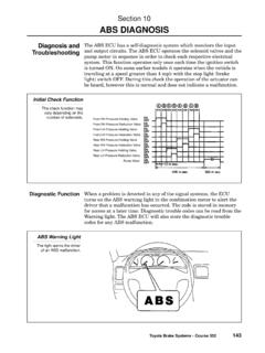
5 (c) Apply a light coat of engine oil on the threads and under A01462 the heads of the bearing cap bolts. (d) 1ZZ FE: Install and uniformly tighten the 19 bearing cap bolts. 6 2 4 8. After tightening the No. 1 camshaft bearing cap, tighten 9. then in several passes, in the sequence shown. 9 Torque: No. 1 23 N m (235 kgf cm, 17 ft lbf). 9 No. 3 13 N m (133 kgf cm, 10 ft lbf). 5 1 3 7. A12962. 2000 CELICA (RM744U). EM 68. ENGINE MECHANICAL cylinder HEAD. (e) 2ZZ GE: Install and uniformly tighten the 20 bearing cap bolts. 20 4 16 8 12 After tightening the No.
6 1 camshaft bearing cap, tighten 19 3 15 7 11 then in several passes, in the sequence shown. 17 1 13 5 9 Torque: N m (189 kgf cm, 14 ft lbf). 18 2 14 6 10 4. CHECK AND ADJUST VALVE CLEARANCE (See page EM 4). 5. INSTALL CAMSHAFT TIMING SPROCKETS AND. A11373 VALVE TIMING CONTROLLER ASSEMBLY (See page EM 25). 6. INSTALL OIL FILTER CAP. 7. INSTALL GROMMET AND PCV VALVE. 8. INSTALL ECT SENSOR (See page SF 63). 9. INSTALL CAMSHAFT POSITION SENSOR (See page IG 10). 10. 1ZZ FE: INSTALL INTAKE MANIFOLD. (a) Install a new gasket, the intake manifold with the 4 bolts and 2 nuts.
7 Torque: N m (189 kgf cm, 14 ft lbf). (b) Connect the brake booster vacuum hose. (c) Connect the EVAP hose for ORVR. A10444. 11. 2ZZ GE: INSTALL INTAKE MANIFOLD. A. A (a) Install the intake manifold insulator to the cylinder block. (b) Install a new gasket, the intake manifold with the 4 bolts A and 2 nuts. A A Torque: A: 27 N m (275 kgf cm, 20 ft lbf). B: 46 N m (469 kgf cm, 34 ft lbf). B A10445 (c) Install the stay with the 2 bolts and nut. Torque: 24 N m (245 kgf cm, 18 ft lbf). (d) Install the oil dipstick and guide with the bolt .
8 Torque: 25 N m (255 kgf cm, 18 ft lbf). (e) Connect the brake booster vacuum hose. (f) Connect the EVAP hose for ORVR. 2000 CELICA (RM744U). EM 69. ENGINE MECHANICAL cylinder HEAD. 12. 1ZZ FE: CONNECT ENGINE WIRE TO cylinder HEAD. (a) Connect the 2 clamps of engine wire to the intake man- ifold. (b) Connect the 2 ground cables. (c) Connect the oil control valve for VVT connector. (d) Connect the camshaft position sensor connector. (e) Connect the ECT sensor connector. A10440. 13. 2ZZ GE: CONNECT ENGINE WIRE TO cylinder HEAD. (a) Install the intake manifold insulator No.
9 2. (b) Connect the 2 ground cables. (c) Connect the oil pressure switch connector. (d) Connect the oil control valve for VVT connector. (e) Connect the oil control valve for VVTL connector. (f) Connect the camshaft position sensor connector. A10441 (g) Connect the ECT sensor connector. (h) Install the accelerator cable bracket with the 2 bolts. 14. INSTALL INJECTORS (See page SF 24). 15. INSTALL THROTTLE BODY (See page SF 39). 16. INSTAL PCV HOSES. 17. INSTALL SPARK PLUGS (See page IG 1). 18. INSTALL IGNITION COIL (See page IG 7).
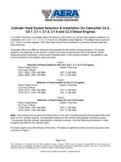
10 19. 1ZZ FE: INSTALL EXHAUST MANIFOLD. (a) Install the lower heat insulator with the 3 bolts. Torque: 12 N m (123 kgf cm, 9 ft lbf). (b) Install a new gasket, and the exhaust manifold with the 5. nuts. Uniformly tighten the nuts in several passes. Torque: 37 N m (377 kgf cm, 27 ft lbf). (c) Install the upper heat insulator with the 6 bolts. A03169 Torque: 12 N m (123 kgf cm, 9 ft lbf). (d) Install the exhaust manifold stay with the 3 bolts. Torque: 49 N m (500 kgf cm, 37 ft lbf). A01034. 2000 CELICA (RM744U). EM 70. ENGINE MECHANICAL cylinder HEAD.