Transcription of INSTALLATION / OPERATION MANUAL - aiproducts.com
1 W w w . S t a l k S t r y k e r . c o m INSTALLATION / OPERATION MANUAL . INTRODUCTION This kit is designed to fit John Deere 600. series corn headers. IMPORTANT: Read through this instruction MANUAL thoroughly and This MANUAL covers all Stalk Stryker row familiarize yourself with the machine configurations available for John Deere 600. before performing any procedures. series headers. Please use the correct sec- tion for your application. Average INSTALLATION time: Average INSTALLATION time for all models is approximately 1 - 4 hours. TABLE OF CONTENTS. Frame Kit Main Components & Hardware List 3 Hardware Kit Components 4. Safety Information 5. Partial Header Coverage A-STR2600 / A-STR2600C 2-row models 6. A-STR4600 / A-STR4600C 4-row models 6. A-STR6600 / A-STR6600C 6-row models 6. Complete Header Coverage A-STR0606 / A-STR0606C 6-row models 8. A-STR0808 / A-STR0808C 8-row models 8.
2 A-STR1212 / A-STR1212C 12-row models (Wide Spacing) 11. A-STR1212N / A-STR1212NC 12-row models (Narrow Spacing) 16. A-STR1616 / A-STR1616C 16-row models 21. A-STR1818 / A-STR1818C 18-row models 27. Down Pressure Setting Instructions 32 Transport & Storage 33. Row Spacing Guide 35. 2. FRAME KIT MAIN COMPONENTS & HARDWARE LIST. Use this chart to identify individual component quantities for the specific frame kit to be installed. FRAME KIT. A-STR1212NC. A-STR1212N. A-STR2600C. A-STR0606C. A-STR4600C. A-STR0808C. A-STR6600C. A-STR1212C. A-STR1616C. A-STR1818C. A-STR2600. A-STR0606. A-STR4600. A-STR0808. A-STR6600. A-STR1212. A-STR1616. A-STR1818. COMPONENT. A-STR402 2 2 2 2 2 2 2 2 2 2 2 2 2 2 2 2 2 2. A-STR327 2 2 2 2 2 2 2 2 2 2 4 4 2 2 4 4 4 4. A-STR32T 2 2. A-STR43T 2 2 2 2 2 2. A-STR74T 2 2 2 2 2 2. A-STR53T 2 2 2 2 4 4 2 2. A-STR90T 2 2 2 2. A-STR28TR 1 1 1 1 1 1 1 1 1 1 1 1.
3 A-STR28TL 1 1 1 1 1 1 1 1 1 1 1 1. A-STR125R 1 1 1 1 1 1 1 1. A-STR125L 1 1 1 1 1 1 1 1. A-STR100B 2 2 6 6 4 4 8 8 6 6 12 12 12 12 16 16 18 18. A-STR101 2 6 4 8 6 12 12 16 18. A-HK402 2 2 2 2 2 2 2 2 2 2 2 2 2 2 2 2 2 2. A-HK327 2 2 2 2 2 2 2 2 2 2 4 4 2 2 4 4 4 4. A-HK182 1 1 1 1. A-HK531 1 1 1 1 2 2 1 1. A-HK280 2 2 2 2 2 2 2 2 2 2 2 2. A-HK125 2 2 2 2 2 2 2 2. A-HK101 2 2 4 4 4 4 6 6 6 6 10 10 8 8 14 14 14 14. A-HK102 4 4 4 4. 3. HARDWARE KIT COMPONENTS. Use this chart to identify individual component quantities for the specific hardware kits used. KITS COMPONENTS. A-HK101 (1) Hitch Pin (2) 5/8 x U-Bolts (1) Lynch Pin (4) 5/8 Serrated Nuts A-HK102 (1) Hitch Pin (2) 5/8 x 2 U-Bolts (1) Lynch Pin (4) 5/8 Serrated Nuts A-HK125 (1) 5/8 x U- bolt (2) 3/8 x 1 NC Bolts (2) 5/8 Flange Nuts (2) 3/8 Serrated Nuts A-HK182 (4) 5/8 x 2 U-Bolts (4) 5/8 x NC Bolts (4) 5/8 Flat Washers A-HK280 (2) Hitch Pins (4) 5/8 Serrated Nuts (2) Lynch Pins A-HK327 (2) 5/8 x 5 U-Bolts (2) 5/8 x U-Bolts (2) 5/8 x 6 U-Bolts (8) 5/8 Serrated Nuts A-HK402 (2) 5/8 x U-Bolts (4) 5/8 Serrated Nuts (2) 1/2 x 2 NC Bolts (2) 1/2 Serrated Nuts A-HK531 (2) 1/2 x NC Bolts (2) 1/2 Serrated Nuts 4.
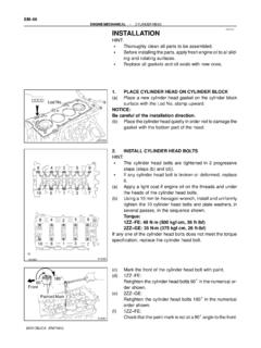
4 Recognize Safety Information This is a safety-alert symbol. When you see this symbol on your machine or in this MANUAL , be alert to the potential for personal injury. Follow recommended precautions and safe operating procedures. Understand Signal Words A signal word - DANGER, WARNING, or CAUTION - DANGER. is used with the safety alert symbol. DANGER identifies the most serious of hazards. WARNING. DANGER or WARNING signs are located near specific hazards. General precautions are listed on CAUTION. safety signs. CAUTION. Follow Safety Instructions Carefully read all safety messages in this MANUAL and in the combine and corn head operators manuals for any instructions and safety messages. Do not let anyone install or use without proper instruction. Park Machine Safely & Prepare Machine for Service Before working on the machine: Attach header to combine Lock header to combine Raise the header Lower safety stops on header lift/feeder cylinders (A).
5 Stop engine & remove key Hang DO NOT OPERATE tag in cab Feeder House Safety Stop CAUTION: Death can occur from a feeder house inadver- tently lowering. Make sure to completely raise the feeder house and verify that the safety stop is fully engaged when installing the Stalk Stryker assembly. To prevent injury, raise feeder house completely and lower safety stop (Identi- fied as A in the imgae at right) onto hydraulic cylinder. 5. INSTALLATION PROCEDURES. A-STR2600 A-STR2600C 2-Row Models A-STR4600 A-STR4600C 4-Row Models A-STR6600 A-STR6600C 6-Row Models A) Attach inside mounting plate A-STR402 to header using hardware kit A-HK402. 1. Attach bracket A-STR402 to header at angle brace next to feeder house hookup using (2) x2 hex bolts and (2) serrated nuts. 2. Position of bracket should be flush on the center side of the brace. As seen below. 3. The (2) 5/8 x u-bolts and 5/8 serrated nuts will be used later for mounting the tool bar.
6 B) Attach standard mounting bracket A-STR327 to header main beam using hardware kit A-HK327. 4. Attach bracket A-STR327 to the main header frame tube using (2) 5/8 u-bolts and (2) 5/8 serrated nuts. Note: the hardware kit is supplied with (2) each of the 5x5 and 6x6 u-bolts. This is to accommodate different serial number headers. Use the pair that fits your header. 5. Please note the location of this bracket. It should be close to the angle support of the header on 2011 and earlier models. On 2012 and later models, position on the main beam as far as possible to the outside with out lining up with a corn row. 6. The (2) 5/8 x u-bolts and corresponding 5/8 serrated nuts will be used later for mounting the tool bar. 6. C) Attach the tool bar A-STR43T or A-STR74T to the brackets assembled in steps 1-6. Note: A-STR43T is used on 2-row and 4 row models, and A-STR74T is used on 6-row models.
7 7. Attach the toolbar A-STR43T (or A-STR74T) to the A-STR402 and A-STR327 bracket using the (4) 5/8 x and 5/8 serrated nuts reserved from steps 3 & 6. Note: holes in tube need to be vertical position. 8. Position toolbar flush on the inside of mounting plate A-STR402. D) Attach Stalk Stryker mount brackets A-STR100B to the toolbar using hardware kit A-HK101. 9. Attach the mounting bracket A-STR100B to the toolbar using (2) 5/8 x u-bolts and 5/8 serrated nuts. This bracket can be mounted in the high or low position depending on cutting height. The high position is recommended as the preferred starting position. The bracket will also need to be centered on the rows. See spacing guide on page 35. 10. The extra hardware (pins and clips) will be used to mount the Stalk Stryker later. E) Attach Stalk Stryker shoes A-STR101 to the A-STR100B bracket. 11. Slide the Stalk Stryker on the A-STR100B bracket and secure with the pin and lynch pin.
8 12. The Stalk Stryker has 8 positions to regulate the down pressure on the ground, as well as the position option of the mounting bracket A-STR100B. Adjustment of down pressure is necessary for the correct OPERATION of the Stalk Stryker . See page 32 for Down Pressure Adjustment instructions. These instructions cover INSTALLATION on one side of the header. Repeat to complete Stalk Stryker INSTALLATION on the opposite side. 7. INSTALLATION PROCEDURES. A-STR0606 A-STR0606C 6-Row Models A-STR0808 A-STR0808C 8-Row Models A) Attach inside mounting plate A-STR402 to header using hardware kit A-HK402. 1. Attach bracket A-STR402 to header at angle brace next to feeder house hookup using (2) x 2 hex bolts and (2) serrated nuts. 2. Position of bracket should be flush on the center side of the brace. As seen below. 3. The (2) 5/8 x u-bolts and 5/8 serrated nuts will be used later for mounting the tool bar.
9 B) Attach standard mounting bracket A-STR327 to header main beam using hardware kit A-HK327. 4. Attach bracket A-STR327 to the main header frame tube using (2) 5/8 u-bolts and (2) 5/8 serrated nuts. Note: the hardware kit is supplied with (2) each of the 5x5 and 6x6 u-bolts. This is to accommodate different serial number headers. Use the pair that fits your header. 5. Please note the location of this bracket. It should be close to the angle support of the header on 2011 and earlier models. On 2012 and later models, position on the main beam as far as possible to the outside with out lining up with a corn row. 6. The (2) 5/8 x u-bolts and corresponding 5/8 serrated nuts will be used later for mounting the tool bar. 8. C) Attach the tool bar A-STR43T or A-STR74T to the brackets assembled in steps 1-6. Note: A-STR43T is used on 6-row models, and A-STR74T is used on 8-row models.
10 7. Attach the toolbar A-STR43T (or A-STR74T) to the A-STR402 and A-STR327 bracket using the (4) 5/8 x and 5/8 serrated nuts reserved from steps 3 & 6. Note: holes in tube need to be vertical position. 8. Position toolbar flush on the inside of mounting plate A-STR402. D) Attach center slide tool bars A-STR28TR and A-STR28TL using hardware kit A-HK280. 9. Attach the left hand slide tube A-STR28TL by sliding it into the A-STR43T tube (or A-STR74T on 8-row) from the feeder house side on the left side of the header. 10. Align holes of A-STR43T / A-STR74T outer tube with hole in the A-STR28TL. Use pin and lynch pin from hardware kit A-HK480 to lock in place after aligning the hole of the outer tube and the second hole of the inner tube. The extra hardware (pins and clips) will be used to mount the Stalk Stryker later. NOTE: This feature will allow the center rows to be slid in for connecting and disconnecting the combine to the header.