Transcription of SECTION 6 FLUID MECHANICS, PUMPS, PIPING, …
1 6 FLUID mechanics , pumps , piping , AND HYDRO POWERPart 1 FLUID and Force on a Plane Force on a Curved of a OF INCOMPRESSIBLE of of Bernoulli s through a Venturi through an through the Suction Pipe of a Drainage of a Flowing over a Sharp-Edged Flow in a Flow in Pipe Application of Darcy-Weisbach of Flow in a Selection by the Manning of Head Caused by Sudden Enlargement of of Looping Flow in Branching Flow in Open Channel Determination of Depth of Canal for Specified FLUID Flow Stages of Flow; Critical of Hydraulic of Change of Depth in Nonuniform between Communicating in Head on a Weir without Inflow to the in Head on a Weir with Inflow to the Analysis Similarity and Construction of 2 Pump Operating Modes, Affinity Laws, Speed, and HeadSeries Pump Installation Pumping or Affinity Laws for Centrifugal or Affinity Laws in Centrifugal Pump Speed Considerations in Centrifugal Pump the Best Operating Speed for a Centrifugal Head on a Pump Handling Vapor-Free Selection for any Pumping of Pump and System Characteristic Positive Suction Head for Hot-Liquid 3 Centrifugal pumps and Hydro PowerMinimum Safe Flow for a Centrifugal a Centrifugal Pump to Handle a Viscous Shaft Deflection and Critical of Liquid Viscosity on Regenerative-Pump of Liquid Viscosity on Reciprocating-Pump of Viscosity and Dissolved Gas on Rotary of Materials for Pump a Hydropneumatic Storage Centrifugal pumps as Hydraulic Centrifugal-Pump Impellers for Safety Choice to Reduce Energy Consumption and Hydro Power
2 Considerations and Clean Energy from Small-Scale Hydro of Solar-Powered pumps in Irrigation and Other 1 FLUID MECHANICSH ydrostaticsThe notational system used in hydrostatics is as follows: W weight of floating body, lb(N);V volume of displaced liquid, ft3(m3);w= specific weight of liquid, lb/ft3(N/m3);for water w lb/ft3(9802 N/m3), unless another value is AND FLOTATIONA timber member 12 ft ( m) long with a cross-sectional area of 90 ( cm2)will be used as a buoy in saltwater. What volume of concrete must be fastened to one mechanics , pumps , piping , AND HYDRO POWERso that 2 ft ( cm) of the member will be above the surface? Use these specificweights: timber 38 lb/ft3(5969 N/m3); saltwater 64 lb/ft3(10,053 N/m3); con-crete 145 lb/ft3(22,777 N/m3).Calculation the weight of the body and the volume of the displaced liquid in terms of the volume of concrete requiredArchimedes principle states that a body immersed in a liquid is subjected to a verticalbuoyant force equal to the weight of the displaced liquid.
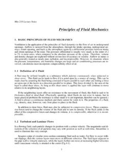
3 In accordance with the equa-tions of equilibrium, the buoyant force on a floating body equals the weight of the ,W Vw(1)Letxdenote the volume of concrete. Then W (90/144)(12)(38) 145x 285 145x;V (90/144)(12 2) x in Eq. 1 and solve for xThus, 285 145x ( x)64;x ft3( m3).HYDROSTATIC FORCE ON A PLANE SURFACEIn Fig. 1, ABis the side of a vessel containing water, and CDEis a gate located in thisplane. Find the magnitude and location of the resultant thrust of the water on the gatewhen the liquid surface is 2 ft ( cm) above the the equations for the resultant magnitude and positionIn Fig. 1, FHdenotes the centroidal axis of area CDEthat is parallel to the liquid surface,andGdenotes the point of application of the resultant force. Point Gis termed the pres-sure area of given surface, (cm2);P hydrostatic force on given surface, lb(N);pm mean pressure on surface, (kPa); yCAandyPC vertical distance fromcentroidal axis and pressure center, respectively, to liquid surface, ft (m); zCAandzPC distance along plane of given surface from the centroidal axis and pressure center, respec-tively, to line of intersection of this plane and the liquid surface, ft (m); ICA moment ofinertia of area with respect to its centroidal axis, ft4(m4).
4 Consider an elemental surface of area dAat a vertical distance ybelow the liquid hydrostatic force dPon this element is normal to the surface and has the magnitudedP wy dA(2)By applying Eq. 2 develop the following equations for the magnitude and position ofthe resultant force on the entire mechanics , pumps , piping , AND HYDRO POWERFIGURE thrust on wyCAA(3)zPC zCA(4) the required values, and solve the equations in step 1 ThusA 1/2(5)(6) 15 ( m2);yCA 2 4 sin 60 ft ( cm);zCA 2 csc 60 4 ft ( cm); ICA/A (bd3/36)/(bd/2) d2/18 2 ( m2);P ( )(15) 5114 lb ( N); zPC 2 ft( cm); yPC sin 60 ft ( cm). By symmetry, the pressurecenter lies on the centroidal axis through alternative equation for PisP pmA(5)Equation 3 shows that the mean pressure occurs at the centroid of the area.
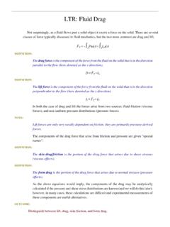
5 The above twosteps constitute method 1 for solving this problem. The next three steps constitute method construct the pressure prism associated with the areaIn Fig. 2, construct the pressure prism associated with area CDE. The pressures are as fol-lows: at apex, p 2w; at base, p (2 6 sin 60 )w force Pequals the volume of this prism, and its action line lies on the centroidalplane parallel to the base. For convenience, resolve this prism into a triangular prism andrectangular pyramid, as P by computing the volume of the pressure prismThus,P Aw[2 2/3( )] Aw(2 ) 15( )( ) 5114 lb (22,747 N). the location of the resultant thrustCompute the distance hfrom the top line to the centroidal plane. Then find yPC. Or, h [2(2/3)(6) (3/4)(6)] ft ( cm); yPC 2 sin 60 ft ( cm).ICA AzCAHYDROSTATIC FORCE ON A CURVED SURFACEThe cylinder in Fig.
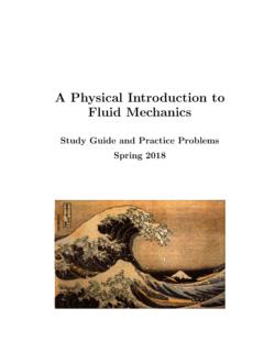
6 3arests on an inclined plane and is immersed in liquid up to its top,as shown. Find the hydrostatic force on a 1-ft ( ) length of cylinder in terms of wand the radius R; locate the pressure the horizontal and vertical component of the force dP on an elemental surface having a central angle d Refer to Fig. 3b. Adopt this sign convention: A horizontal force is positive if directed tothe right; a vertical force is positive if directed upward. The first three steps constitutemethod wR2(sin sin cos )d ;dPV wR2( cos cos2 )d . these equations to obtain the resultant forces PHand PV; then find PHere,PH wR2[( cos 1/2cos2 )]07 /6 wR2[ ( 1) 1/2( 1)] , to right; PV wR2( sin 1/2 1/4sin 2 )7 /60 wR2( ) ( ) , upward; P wR2( ) the value of at the pressure centerSince each elemental force dPpasses through the center of the cylinder, the resultantforcePalso passes through the center.
7 Thus, tan (180 PC) PH/PV ; PC 145 41 . PHand PVApply these principles: PH force on an imaginary surface obtained by projecting thewetted surface on a vertical plane; PV weight of real or imaginary liquid lying be-tween the wetted surface and the liquid surface. Use the plus sign if the realliquid lies be-low the wetted surface and the minus sign if it lies above this force, to right, on AC force, to left, on EC force, to right, on AE;AE ;pm ;PH ( ) ;PV weight of MECHANICSFIGURE 3liquid above GCB weight of real liquid above GA weight of imaginary liquid in cylin-drical sector AOBGand in prismoid, AOBF. Volume of sector AOBG [(7 /6)/(2 )]( R2) ; volume of prismoid AOBF 1/2( )(R ) ;PV wR2( ) OF A VESSELThe boat in Fig. 4 is initially floating upright in freshwater.
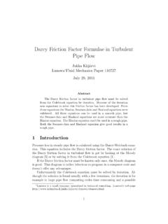
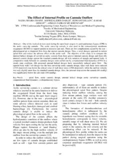
8 The total weight of the boatand cargo is 182 long tons (1813 kN); the center of gravity lies on the longitudinal ( ,the fore-and-aft) axis of the boat and ft ( cm) above the bottom. A wind causesthe boat to list through an angle of 6 while the cargo remains stationary relative to theboat. Compute the righting or upsetting moment (a) without applying any set equation;(b) by applying the equation for metacentric the displacement volume and draft when the boat is uprightThe buoyant force passes through the center of gravity of the displaced liquid; this pointis termed the center of 5 shows the cross SECTION of a boat rotatedthrough an angle . The center of buoyancy for the upright position is B;B is the centerof buoyancy for the position shown, and Gis the center of gravity of the boat and the position indicated in Fig.
9 5, the weight Wand buoyant force Rconstitute a cou-ple that tends to restore the boat to its upright position when the disturbing force is re-moved; their moment is therefore termed these forces constitute a couplethat increases the rotation, their moment is said to be wedges OACandOA C are termed the wedge of emersionandwedge of immersion,respectively. Let h horizontal displacement of center of buoyancy caused by rotation; h mechanics , pumps , piping , AND HYDRO POWERFIGURE 4distance between centroids of wedgeof emersion and wedge of immer-sion;V volume of wedge ofemersion (or immersion). Thenh (6)The displacement volume and thedraft when the boat is upright are W 182 (2240) lb (1813 N); V W/w 6530 ft3( m3);d 6530/[64(20)] ft ( cm). h, using Eq.
10 6 Since is relatively small, apply thisapproximation:h 2b/3 2(20)/3 ft ( cm), h 1/2(10)(10 tan 6 ) ( )/[ (20)] ft ( cm). the horizontal distance a (Fig. 5)Thus,BG 1/2( ) ft ( cm); a sin 6 ft ( cm). the moment of the vertical forcesThus,M W(h a) 407,700( ) 22,400 ft lb (30, N m). Since h>a, themoment is righting. This constitutes the solution to part a. The remainder of this procedureis concerned with part Fig. 5, let Mdenote the point of intersection of the vertical line through B and thelineBGprolonged. Then Mis termed the metacenterassociated with this position, and thedistanceGMis called the metacentric positive if Gis above B, and GMis positive if Mis above G. Thus, the moment of vertical forces is righting or upsetting de-pending on whether the metacentric height is positive or negative, the lever arm of the vertical forcesUse the relation for metacentric height:GM BG(7)whereIWL moment of inertia of original waterline SECTION about axis through O.