Transcription of FLUID MECHANICS 203 - FREE STUDY
1 1 Unit 41: FLUID MECHANICS Unit code: T/601/1445 QCF Level: 4 Credit value: 15 OUTCOME 3 TUTORIAL 3 - THE FLOW OF REAL FLUIDS 3 Be able to determine the behavioural characteristics and parameters of real FLUID flow Head losses: head loss in pipes by Darcy s formula; Moody diagram; head loss due to sudden enlargement and contraction of pipe diameter; head loss at entrance to a pipe; head loss in valves; flow between reservoirs due to gravity; hydraulic gradient; siphons; hammerblow in pipes Reynolds number: inertia and viscous resistance forces; laminar and turbulent flow; critical velocity Viscous drag: dynamic pressure; form drag; skin friction drag; drag coefficient Dimensional analysis: checking validity of equations such as those for pressure at depth; thrust on immersed surfaces and impact of a jet; forecasting the form of possible equations such as those for Darcy s formula and critical velocity in pipes CONTENTS 1.
2 PIPE FLOW Conservation of Mass Conservation of Energy Energy Forms Bernoulli s Equation Hydraulic Gradient Laminar and Turbulent Flow Laminar Flow Turbulent Flow Laminar and Turbulent Boundary Layers Critical Velocity Reynolds No. Derivation of Poiseuille s Equation for Laminar Flow Friction Coefficient Dynamic Pressure Wall Shear Stress Friction Coefficient for Laminar Flow Darcy Formula FLUID Resistance Moody Diagram and Relative Surface Roughness Minor Losses Coefficient Of Contraction Cc Coefficient Of Velocity Cv Exit from a Pipe into a Tank. Entry to a Pipe from a Tank Sudden Enlargement Sudden Contraction Bends and Fittings Siphons Momentum and Pressure Forces 2.
3 WATER HAMMER Bulk Modulus Speed of Sound in an Elastic Medium Pressure Surges Due to Gradual Closure Pressure Surges Due to Sudden Closure The Effect of Elasticity in Pipe Damping Out Pressure Surges This is a very large outcome requiring a lot of STUDY time. The tutorial may contain more material than needed by those who have already studied the appropriate pre-requisite material. Let's start by revising basics. 2 1. PIPE FLOW The solution of pipe flow problems requires the applications of two principles, the law of conservation of mass (continuity equation) and the law of conservation of energy (Bernoulli s equation) CONSERVATION OF MASS When a FLUID flows at a constant rate in a pipe or duct, the mass flow rate must be the same at all points along the length.
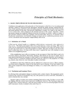
4 Consider a liquid being pumped into a tank as shown ( ). The mass flow rate at any section is m = Aum = density (kg/m3) um = mean velocity (m/s) A = Cross Sectional Area (m2) For the system shown the mass flow rate at (1), (2) and (3) must be the same so 1A1u1 = 2A2u2 = 3A3u3 In the case of liquids the density is equal and cancels so A1u1 = A2u2 = A3u3 = Q CONSERVATION OF ENERGY ENERGY FORMS FLOW ENERGY This is the energy a FLUID possesses by virtue of its pressure. The formula is = pQ Joules p is the pressure (Pascals) Q is volume rate (m3) 3 POTENTIAL OR GRAVITATIONAL ENERGY This is the energy a FLUID possesses by virtue of its altitude relative to a datum level. The formula is = mgz Joules m is mass (kg) z is altitude (m) KINETIC ENERGY This is the energy a FLUID possesses by virtue of its velocity.
5 The formula is = mum2 Joules um is mean velocity (m/s) INTERNAL ENERGY This is the energy a FLUID possesses by virtue of its temperature. It is usually expressed relative to 0oC. The formula is U = mc c is the specific heat capacity (J/kg oC) is the temperature in oC In the following work, internal energy is not considered in the energy balance. SPECIFIC ENERGY Specific energy is the energy per kg so the three energy forms as specific energy are as follows. = pQ/m = p/ Joules/kg = gz Joules/kg = u2 Joules/kg ENERGY HEAD If the energy terms are divided by the weight mg, the result is energy per Newton. Examining the units closely we have J/N = N m/N = metres. It is normal to refer to the energy in this form as the energy head.
6 The three energy terms expressed this way are as follows. = p/ g = h = z = u2 /2g The flow energy term is called the pressure head and this follows since earlier it was shown p/ g = h. This is the height that the liquid would rise to in a vertical pipe connected to the system. The potential energy term is the actual altitude relative to a datum. The term u2/2g is called the kinetic head and this is the pressure head that would result if the velocity is converted into pressure. 4 BERNOULLI S EQUATION Bernoulli s equation is based on the conservation of energy. If no energy is added to the system as work or heat then the total energy of the FLUID is conserved. Remember that internal (thermal energy) has not been included.
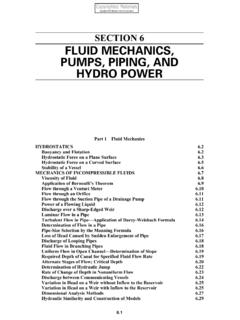
7 The total energy ET at (1) and (2) on the diagram ( ) must be equal so : 2ummgzQp2ummgzQpE2222221111T Dividing by mass gives the specific energy form 2ugzp2ugzpmE2222221111T Dividing by g gives the energy terms per unit weight g2uzgpg2uzgpmgE2222221111T Since p/ g = pressure head h then the total head is given by the following. g2uzhg2uzhh22222111T This is the head form of the equation in which each term is an energy head in metres. z is the potential or gravitational head and u2/2g is the kinetic or velocity head. For liquids the density is the same at both points so multiplying by g gives the pressure form. The total pressure is as follows. 2ugzp2ugzpp22222111T In real systems there is friction in the pipe and elsewhere.
8 This produces heat that is absorbed by the liquid causing a rise in the internal energy and hence the temperature. In fact the temperature rise will be very small except in extreme cases because it takes a lot of energy to raise the temperature. If the pipe is long, the energy might be lost as heat transfer to the surroundings. Since the equations did not include internal energy, the balance is lost and we need to add an extra term to the right side of the equation to maintain the balance. This term is either the head lost to friction hL or the pressure loss pL. L22222111hg2uzhg2uzh The pressure form of the equation is as follows. L22222111p2ugzp2ugzp The total energy of the FLUID (excluding internal energy) is no longer constant.
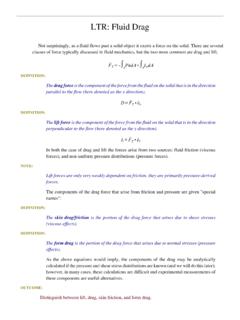
9 Note that if one of the points is a free surface the pressure is normally atmospheric but if gauge pressures are used, the pressure and pressure head becomes zero. Also, if the surface area is large (say a large tank), the velocity of the surface is small and when squared becomes negligible so the kinetic energy term is neglected (made zero). 5 WORKED EXAMPLE No. 1 The diagram shows a pump delivering water through as pipe 30 mm bore to a tank. Find the pressure at point (1) when the flow rate is dm3/s. The density of water is 1000 kg/m3. The loss of pressure due to friction is 50 kPa. SOLUTION Area of bore A = x = x 10-6 m2. Flow rate Q = dm3/s = m3/s Mean velocity in pipe = Q/A = m/s Apply Bernoulli between point (1) and the surface of the tank.
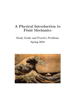
10 Lpugzpugzp 2222222111 Make the low level the datum level and z1 = 0 and z2 = 25. The pressure on the surface is zero gauge pressure. PL = 50 000 Pa The velocity at (1) is m/s and at the surface it is zero. pressure gauge WORKED EXAMPLE 2 The diagram shows a tank that is drained by a horizontal pipe. Calculate the pressure head at point (2) when the valve is partly closed so that the flow rate is reduced to 20 dm3/s. The pressure loss is equal to 2 m head. 6 SOLUTION Since point (1) is a free surface, h1 = 0 and u1 is assumed negligible. The datum level is point (2) so z1 = 15 and z2 = 0. Q = m3/s A2 = d2/4 = x ( )/4 = x 10-3 m2. u2 = Q/A = x 10-3 = m/s Bernoulli s equation in head form is as follows.