Transcription of Selecting Target ISO Cleanliness Codes
1 Set the Target . The first step in identifying a Target ISO code for a system is to identify the most sensitive on an individual system, or the most sensitive component supplied by a central reservoir. If a central reservoir supplies several systems the overall Cleanliness must be maintained, or the most sensitive component must be protected by filtration that cleans the fluid to the Target before reaching that component. Selecting Target ISO Cleanliness Codes When setting Target ISO fluid Cleanliness Codes for hydraulic and lubrication systems it is important keep in mind the objectives to be achieved. Maximizing equipment reliability and safety, minimizing repair and replacement costs, extending useful fluid life, satisfying warranty requirements, and minimizing production down-time are attainable goals. Once a Target ISO Cleanliness code is set following a progression of steps to achieve that Target , monitor it, and maintain it justifiable rewards will be yours.
2 Pressure Media Pressure Media Pressure Media < 140 bar x[c] = 1000 212 bar x[c] = 1000 > 212 bar x[c] = 1000 Pumps < 2000 psi ( x = 200) 3000 psi ( x = 200) > 3000 psi ( x = 200) Fixed Gear 20/18/15 22 [c] (25 ) 19/17/15 12 [c] (12 ) - - Fixed Piston 19/17/14 12 [c] (12 ) 18/16/13 12 [c] (12 ) 17/15/12 7 [c] (6 ) Fixed Vane 20/18/15 22 [c] (25 ) 19/17/14 12 [c] (12 ) 18/16/13 12 [c] (12 ) Variable Piston 18/16/13 7 [c] (6 ) 17/15/13 5 [c] (3 ) 16/14/12 7 [c] (6 ) Variable Vane 18/16/13 7 [c] (6 ) 17/15/12 5 [c] (3 ) - - Valves Cartridge 18/16/13 12 [c] (12 ) 17/15/12 7 [c] (6 ) 17/15/12 7 [c] (6 ) Check Valve 20/18/15 22 [c] (25 ) 20/18/15 22 [c] (25 ) 19/17/14 12 [c] (12 ) Directional (solenoid) 20/18/15 22 [c] (25 ) 19/17/14 12 [c] (12 ) 18/16/13 12 [c] (12 ) Flow Control 19/17/14 12 [c] (12 ) 18/16/13 12 [c] (12 ) 18/16/13 12 [c] (12 ) Pressure Control (modulating) 19/17/14 12 [c] (12 ) 18/16/13 12 [c] (12 ) 17/15/12 7 [c] (6 ) Proportional Cartridge Valve 17/15/12 7 [c] (6 ) 17/15/12 7 [c] (6 ) 16/14/11 5 [c] (3 ) Proportional Directional 17/15/12 7 [c] (6 ) 17/15/12 7 [c] (6 ) 16/14/11 5 [c] (3 ) Proportional Flow Control 17/15/12 7 [c] (6 ) 17/15/12 7 [c] (6 ) 16/14/11 5 [c] (3 ) Proportional Pressure Control 17/15/12 7 [c] (6 ) 17/15/12 7 [c] (6 ) 16/14/11 5 [c] (3 ) Servo Valve 16/14/11 7 [c] (6 ) 16/14/11 5 [c] (3 ) 15/13/10 5 [c] (3 ) Bearings Ball Bearing 15/13/10 5 [c] (3 ) - - - - Gearbox (industrial) 17/16/13 12 [c] (12 ) - - - - Journal Bearing (high speed) 17/15/12 7 [c] (6 ) - - - - Journal Bearing (low speed) 17/15/12 7 [c] (6 )
3 - - - - Roller Bearing 16/14/11 7 [c] (6 ) - - - - Actuators Cylinders 17/15/12 7 [c] (6 ) 16/14/11 5 [c] (3 ) 15/13/10 5 [c] (3 ) Vane Motors 20/18/15 22 [c] (25 ) 19/17/14 12 [c] (12 ) 18/16/13 12 [c] (12 ) Axial Piston Motors 19/17/14 12 [c] (12 ) 18/16/13 12 [c] (12 ) 17/15/12 7 [c] (6 ) Gear Motors 20/18/14 22 [c] (25 ) 19/17/13 12 [c] (12 ) 18/16/13 12 [c] (12 ) Radial Piston Motors 20/18/15 22 [c] (25 ) 19/17/14 12 [c] (12 ) 18/16/13 12 [c] (12 ) Test Stands, Hydrostatic Test Stands 15/13/10 5 [c] (3 ) 15/13/10 5 [c] (3 ) 15/13/10 5 [c] (3 ) Hydrostatic Transmissions 17/15/13 7 [c] (6 ) 16/14/11 5 [c] (3 ) 16/14/11 5 [c] (3 ) Recommended* Target ISO Cleanliness Codes and media selection for systems using petroleum based fluids per ISO4406:1999 for particle sizes 4 [c] / 6 [c] / 14 [c] Other Considerations Table 1 recommends conservative Target ISO Cleanliness Codes based on a several component manufacturers guidelines and extensive field studies for standard industrial operating conditions in systems using petroleum based fluids.
4 If a non-petroleum based fluid is used ( water glycol) the Target ISO code should be set one value lower for each size (4 [c]/6 [c]/14 [c]). If a combination of the following conditions exists in the system the Target ISO code should also be set one value lower: Component is critical to safety or overall system reliability. Frequent cold start. Excessive shock or vibration. Other Severe operation conditions. Example ISO Code Comments Operating Pressure 156 bar, 2200 psi Most Sensitive Component Directional Solenoid 19/17/14 recommended baseline ISO Code Fluid Type Water Glycol 18/16/13 Adjust down one class Operating Conditions Remote location, repair difficult Adjust down one class, combination High ingression rate 17/15/12 of critical nature, severe conditions *Depending upon system volume and severity of operating conditions a combination of filters with varying degrees of filtration efficiency might be required ( pressure, return, and off-line filters) to achieve and maintain the desired fluid Cleanliness .
5 Click here to return to website Precision Filtration Products Box 218 Pennsburg, PA 18073 Phone: 215-679-6645 Fax: 215-679-6648 E-mail: web site: TargetTargetTargetTargetISO CodeISO CodeISO CodeISO CodeISO Code2 x Life3 x Life4 x Life5 x Life28/26/2325/22/1922/20/1720/18/1519/1 7/1427/25/2223/21/1821/19/1619/17/1418/1 6/1326/24/2122/20/1720/18/1519/17/1417/1 5/1225/23/2021/19/1619/17/1417/15/1216/1 4/1125/22/1920/18/1518/16/1316/14/1115/1 3/1023/21/1819/17/1417/15/1215/13/1014/1 2/9 Accurate oil analysis - Once the Target ISO fluid Cleanliness code is established it is critical to properly measure the actual Cleanliness of the system. A well designed plan to achieve Cleanliness can be undermined if steps are not taken to ensure accurate and repeatable oil analysis. When sampling the oil a wide range of variables can affect the outcome yielding inaccurate results.
6 For more information see Accurate oil sampling and analysis article. Extending Roller Bearing Life. Improving fluid Cleanliness in lubrication systems for roller bearings can exponentially increase component life. Figure B describes attainable increases in life expectancy of roller bearings as improvements in ISO fluid Cleanliness Codes are made. Life extension for hydraulic components can be achieved by improving fluid Cleanliness . Oil sampling methods and practices - Bottle samples analyzed by independent laboratories is common and widely accepted as a method of quantifying fluid Cleanliness . However, there are many variables associated with bottle sampling that can cause inaccurate readings. Background contamination in clean sample bottles or vacuum tubes can increase ISO Codes by 1~4 classes per size measured, 4 [c]/6 [c]/14 [c]. Inconsistent in-plant sampling practices ( sample port flush time, bottle rinsed or not).
7 Exposure of sample to airborne contaminate during sampling and analysis Analysis lab procedure repeatability by operator ( agitation~count interval affect on suspension). Analysis lab calibration drift. Variability between oil analysis lab particle Oil sampling port types and locations - Just as sampling technique and method can compromise results, sampling port and location can also be a challenge. Sampling ports are often contamination collection points and must be flushed for up to 6 minutes before a truly representative sample is captured. Without a proper port flush the results can be affected. Port location is also critical to obtaining a good sample. Locating a sampling where there is turbulent flow will provide more realistic results than a laminar area. For more information see Accurate oil sampling and analysis article. On-line particle counting - Connecting an on-line particle counter directly to the hydraulic or lube system through sampling ports provides the most accurate snapshot of fluid Cleanliness and eliminates many of the inherent variables associated with bottle sampling.
8 Some particle counters can function with system pressure as low as 20 psi ( bar) at certain viscosities for sampling pressure line, return line, or lubrication system. There are also particle counter options available to draw (Sip) the fluid from a reservoir, tote, or other container directly into the particle counter when system pressure is not available. Monitor sample port Cleanliness in real time to know when the sample is truly representative of the system and not tainted with sample port contaminate buildup. Maintaining control of the sampling and analysis procedures increases the accuracy of your results, eliminates the waiting game to get samples back from a lab, allows quicker response to contamination related issues, and even save money on oil sample kits. No one knows your system better than you and once armed with the right oil analysis approach and diagnostic equipment you can make improvements in reliability.
9 PTK-1 Oil analysis kit - Patch test kits are a good complement to on-line particle counters as they provide the capability to visually analyze contamination levels and types in the system. The kit includes a microscope, vacuum pump, test patches, and solvent dispenser integrated into a carrying case. The kit also features a reference manual to correlate visual patch appearance to approximate ISO code. click here to return to website Precision Filtration Products Box 218 Pennsburg, PA 18073 Phone: 215-679-6645 Fax: 215-679-6648 E-mail: web site: Pressure filters are ideal for protecting control valves and other sensitive components from internally generated contaminate and ingression. Machine tools without a pressure filter protecting valve manifolds after the pump. Power units on CNC lathes and milling equipment, Plastics injection molding, mobile equipment, and other small industrial machines with sensitive control valves.
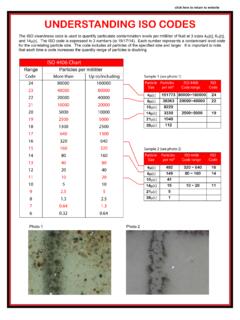
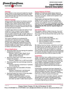
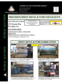
10 Focus: Solving contamination issues resulting from insufficient filtration on power units and machine tools. Machine Tool Contamination Field Study The Problem - Insufficient filtration APPLICATIONS Machine tools and power units are frequently designed without the filtration necessary to maintain recommended fluid Cleanliness levels for the system. A fluid Cleanliness case study of three CNC lathes (A, B, C) raised some concern. The only filtration present was either a coarse suction strainer or coarse return-line screen. Baseline oil analysis (see fig 1) revealed that the fluid Cleanliness levels of the hydraulic fluids (per ISO 4406 code chart) were higher than recommended levels for the system components (see fig 2). fig. 1 Machine ISO code* A 22 / 20 / 14 B 23 / 20 / 14 C 23 / 21 / 16 fig 2. Pumps <2000 psi 2000~3000 >3000 psi Fixed gear 20/18/15 19/17/15 Fixed vane 20/18/15 19/17/14 18/16/13 Fixed piston 19/17/14 18/16/13 17/15/12 Variable vane 18/16/13 17/15/12 Variable piston 18/16/13 17/15/13 16/14/12 Valves 2000~3000 >3000 psi Directional (solenoid) 20/18/15 19/17/14 Proportional 17/15/12 16/14/11 Servo Valve 16/14/11 15/13/10 Contamination Basics & Sources Particulate contamination is the number one cause of hydraulic component failure, and 70~75% of failures are related to surface degradation caused by mechanical wear.