Transcription of self-Regulating Heating Cable
1 self - regulating Heating Cable Complex piping Design Guide self - regulating Heating Cable Complex Piping Design Guide Contents Introduction .. 2. Application Information .. 2. Heat Tracing Design Outline ..3-12. Basis for a Good Design Step 1: Establish Design 3. Step 2: Determine Heat 4-5. Step 3: Select the Proper Thermon Heating Step 4: Determine Heat Tracing Circuit Step 5: Choose 12. Design Tips .. 13. Design Worksheet ..14-15. General Specification .. 16-17. This Design Guide displays information in English and metric values wher- ever possible. Certain tables have been displayed in English values only due to space constraints. Contact Thermon to obtain these tables in metric values. self - regulating Heating Cable Introduction .. HTSX .. Designed for process temperature maintenance or freeze protection applications up to 250 F (121 C) and with- This design guide addresses the heat tracing requirements of stand intermittent exposure temperatures (power-on) up to complex piping.
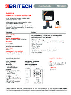
2 Whether the application is a small project or a 420 F (215 C), intermittent exposure temperatures (power-off). complete network of piping and equipment, designing an elec- up to 482 F (250 C) and continuous exposure (power-off) to tric heat tracing system for complex piping is simplified by us- 400 F (204 C). The Cable is capable of withstanding the expo- ing Thermon self - regulating cables. The information contained sure temperatures associated with steam purging. in this design guide will take the reader through a step-by-step procedure to make proper Heating Cable selections based on: 1. Nickel-Plated Copper Bus Wires 3 1 2. Semiconductive Heating Matrix and Pipe size Minimum ambient temperature 4 2 Fluoropolymer Dielectric Insulation Thermal insulation type Heating Cable start-up temperature 3.
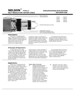
3 Tinned Copper Braid 4. Fluoropolymer Overjacket and thickness Available power supply Desired maintenance temperature Electrical area classification Maximum exposure temperature VSX .. Designed for process temperature maintenance or freeze protection applications up to 300 F (149 C) and with- After following the prescribed steps in this design guide, the stand intermittent exposure temperatures (power-on) up to reader will be able to design, select and/or specify or establish 450 F (232 C), intermittent exposure temperatures (power-off). a bill of materials for a heat tracing system. up to 482 F (250 C) and continuous exposure (power-off) to Typically, complex piping is located inside a process unit and 400 F (204 C). consists of relatively short runs of pipe with frequent tees, as 1.
4 Nickel-Plated Copper Bus Wires 2. Semiconductive Heating Matrix and well as in-line valves, pumps and related process equipment 3 1 Fluoropolymer Dielectric Insulation 4 2. that also requires heat tracing. Circuit lengths can range from 3. Nickel-Plated Copper Braid 4. High Temperature several feet (less than one meter) to several hundred feet (me- Fluoropolymer Overjacket ters) in length; however, the average is usually 100 feet (30. meters) or less. For applications ranging from freeze protecting water lines to Computer Aided Design Program .. maintaining elevated process temperatures as high as 300 F Thermon has developed a sophisticated yet easy-to-use com- (149 C), Thermon self - regulating , cut-to-length, parallel resis- puter program, CompuTrace , that provides detailed design tance Heating cables are recommended.
5 Variations in the heat and performance information. Users of CompuTrace are able loss of the insulated pipe (due to equipment, supports and/or to input application-specific information into the program and insulation) are compensated for by the Heating Cable 's PTC obtain detailed electrical and thermal performance information. (Positive Temperature Coefficient) characteristic. Thermon of- Calculations made within the program are based on the formu- fers Heating cables specifically designed, manufactured and las prescribed in IEEE Standard 515-2004. approved to cover a wide range of applications. The information input to and/or generated from Compu- BSX .. Designed for freeze protection and temperature Trace can be printed and summary reports, including load maintenance at or below 150 F (65 C), BSX is well-suited for chart information, exported for use in other programs.
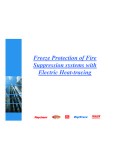
6 While both metallic and nonmetallic piping and equipment. CompuTrace is a valuable asset to use in designing a heat trac- 1. Nickel-Plated Copper Bus Wires ing system, the design steps detailed in this guide will still form 1 2. Radiation Cross-Linked Semiconductive Heating Matrix the basis for identifying the design process necessary to estab- 5 3. 4 2 3. Polyolefin Dielectric Insulation lish a properly functioning heat tracing system. 4. Tinned Copper Braid 5. Polyolefin or Fluoropolymer Overjacket RSX 15-2 .. Designed for applications where the watt den- sity requirements preclude the use of the standard range of BSX cables. 1. Nickel-Plated Copper Bus Wires 1 2. Radiation Cross-Linked Semiconductive 3 Heating Matrix 5 2 3. Polyolefin Dielectric Insulation 4.
7 4. Tinned Copper Braid 5. Polyolefin or Fluoropolymer Overjacket . Complex piping Design Guide Heat Tracing Complex Piping Design Outline .. Basis for a Good Design .. The five steps below outline the design and selection process To become familiar with the requirements of a properly de- for an electric heat tracing system. The step-by-step proce- signed electric heat tracing system, use the five design steps dures that follow the outline will provide the reader with the detailed here and on the following pages. Once comfortable detailed information required to design, select and/or specify with the steps and the information required, use the design a fully functional electrical heat tracing system. worksheet included at the end of this design guide for applying these steps to a complex piping application.
8 Step 1: Establish Design Parameters Collect relevant project data: Step 1: Establish Design Parameters a. Piping/equipment Collect information relative to the following design parameters: Diameter Length Material 1. b. Temperature Application Information .. Low ambient Start-up temperature Pipe sizes or tubing diameters Maintain temperature Pipe lengths High temperature Limits/excursions Pipe material (metallic or nonmetallic). c. Insulation Type and number of valves, pumps or other equipment Type Thickness Oversized? Type and number of pipe supports d. Electrical Expected Minimum Ambient Temperature .. Generally, this Operating voltage Circuit breaker capacity number is obtained from weather data compiled for an area Electrical area classification and is based on recorded historical data.
9 There are times, how- Step 2: Determine Heat Losses ever, when the minimum ambient will not be the outside air Using information gathered in Step 1 and based on: temperature. Examples include pipes and equipment located a. Heat loss charts/tables underground or inside buildings. b. Computer design programs CompuTrace Minimum Start-Up Temperature .. This temperature differs Step 3: Select the Proper Thermon Heating Cable from the minimum expected ambient in that the Heating Cable Based on: will typically be energized at a higher ambient temperature. a. Application requirements This temperature will have an effect on the maximum circuit Maintain temperature length and circuit breaker sizing for a given application (see Maximum exposure temperature Circuit Length Tables on pages 7-10 ).
10 B. Watt density requirements Insulation Material and Thickness .. The selection charts in Power output at maintain temperature this design guide are based on fiberglass insulation with thick- c. Electrical design nesses shown in Tables through If insulation materials Available voltage other than fiberglass are used, refer to the insulation correction Circuit breaker capacity factors shown in Table or contact Thermon or a Thermon Cold start impact factory representative for design assistance. d. Approval requirements Hazardous area approval Code requirements Supply Voltage .. Thermon self - regulating cables are de- signed in two voltage groups: 110-130 Vac and 208-277 Vac. Step 4: Determine Heat Tracing Circuit Lengths Determine what voltage(s) are available at a facility for use with Based on Cable selection, electrical design and pipe heat tracing.