Transcription of Semiconductor Corporation Digital Audio Interface …
1 CS8411 CS8412. Semiconductor Corporation Digital Audio Interface Receiver Features General Description: Monolithic CMOS Receiver The CS8411/12 are monolithic CMOS devices which re- ceive and decode Audio data according to the AES/EBU, IEC 958, S/PDIF, & EIAJ CP-340 Interface Low-Jitter, On-Chip Clock Recovery standards. The CS8411/12 receive data from a trans- mission line, recover the clock and synchronization 256 Fs Output Clock Provided signals, and de-multiplex the Audio and Digital data. Dif- Supports: ferential or single ended inputs can be decoded.
2 AES/EBU, IEC 958, The CS8411 has a configurable internal buffer memory, S/PDIF, & EIAJ CP-340 read via a parallel port, which may be used to buffer Professional and Consumer Formats channel status, auxiliary data, and/or user data. Extensive Error Reporting Repeat Last Sample on Error Option The CS8412 de-multiplexes the channel, user, and va- lidity data directly to serial output pins with dedicated output pins for the most important channel status bits. On-Chip RS422 Line Receiver ORDERING INFORMATION: page 33. Configurable Buffer Memory (CS8411) TABLE OF CONTENTS: page 34.
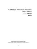
3 VD+ DGND VA+ FILT AGND MCK. 7 8 22 20 21 19 26. CS8411 SDATA. Audio 12. SCK. Serial Port 11. FSYNC. 13. 9 A4/FCK. RXP RS422 4. Clock & Data 10 De-Mux A3 - A0. RXN Receiver Recovery Configurable 8. D7- D0. Buffer Memory 24 CS. IEnable & Status 23 RD/WR. 25 14. ERF INT. VD+ DGND VA+ FILT AGND MCK M3 M2 M1 M0. 7 8 22 20 21 19 17 18 24 23. CS8412. 26 SDATA. Audio 12. SCK. Serial Port 11. 9 FSYNC. RXP RS422 Clock & Data 10 De-Mux RXN Receiver Recovery 1. C. 14. Registers U. Mux Mux 28. VERF. 13 16 6 5 4 3 2 27 25 15. CS12/ SEL C0/ Ca/ Cb/ Cc/ Cd/ Ce/ ERF CBL.
4 FCK E0 E1 E2 F0 F1 F2. This document contains information for a new product. Crystal Preliminary Product Information Semiconductor reserves the right to modify this product without notice. Crystal Semiconductor Corporation NOV '93. Box 17847, Austin, TX 78760 DS61PP4. (512) 445-7222 FAX: (512) 445-7581 1. CS8411 CS8412. ABSOLUTE MAXIMUM RATINGS (GND = 0V, all voltages with respect to ground). Parameter Symbol Min Max Units Power Supply Voltage VD+, VA+ V. Input Current, Any Pin Except Supply Note 1 Iin 10 mA. Input Voltage, Any Pin except RXP, RXN VIN VD+ + V.
5 Input Voltage, RXP and RXN VIN -12 12 V. Ambient Operating Temperature (power applied) TA -55 125 C. Storage Temperature Tstg -65 150 C. Notes: 1. Transient currents of up to 100 mA will not cause SCR latch-up. WARNING: Operation beyond these limits may result in permanent damage to the device. Normal operation is not guaranteed at these extremes. RECOMMENDED OPERATING CONDITIONS. (GND = 0V; all voltages with respect to ground). Parameter Symbol Min Typ Max Units Power Supply Voltage VD+, VA+ V. Supply Current VA+ IA 20 35 mA.
6 VD+ ID 7 10 mA. Ambient Operating Temperature: CS8411/12-CP or -CS Note 2 TA 0 25 70 C. CS8411/12-IP or -IS -40 85 C. Power Consumption PD 135 248 mW. Notes: 2. The '-CP' and '-CS' parts are specified to operate over 0 to 70 C but are tested at 25 C only. The '-IP' and '-IS' parts are tested over the full -40 to 85 C temperature range. Digital CHARACTERISTICS. (TA = 25 C for suffixes '-CP' & '-CS', TA = -40 to 85 C for '-IP' VD+, VA+ = 5V 10%). Parameter Symbol Min Typ Max Units High-Level Input Voltage except RXP, RXN VIH V.
7 Low-Level Input Voltage except RXP, RXN VIL + V. High-Level Output Voltage (IO = 200 A) VOH VD+ - V. Low-Level Output Voltage (IO = ) VOL V. Input Leakage Current Iin 10 A. Input Sample Frequency (Note 3) CS8411/12-CP or -CS FS 25 55 kHz CS8411/12-IP or -IS FS 30 50 kHz Master Clock Frequency Note 3 MCK 256 FS MHz MCK Clock Jitter tj 200 ps RMS. MCK Duty Cycle (high time/cycle time) 50 %. Notes: 3. FS is defined as the incoming Audio sample frequency per channel. Specifications are subject to change without notice. 2 DS61PP4.
8 CS8411 CS8412. Digital CHARACTERISTICS - RS422 RECEIVERS. (RXP, RXN pins only; VD+, VA+ = 5V 10%). Parameter Symbol Min Typ Max Units Input Resistance (-7V < VCM < 7V) Note 4 ZIN 10 k . Differential Input Voltage, RXP to RXN (-7V < VCM < 7V) Note 4,5 VTH 200 mV. Input Hysteresis VHYST 50 mV. Notes: 4. VCM - Input Common Mode Range 5. When the receiver inputs are configured for single ended operation ( consumer configuration) the signal amplitude must exceed 400mVp-p for the differential voltage on RXP to RXN to exceed 200mV.
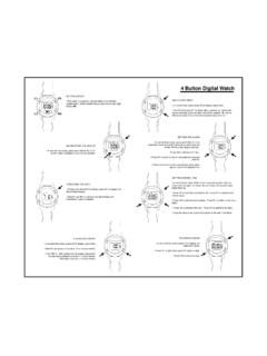
9 This represents SWITCHING CHARACTERISTICS - CS8411 PARALLEL PORT. (TA = 25 C for suffixes '-CP' and '-CS'; TA = -40 to 85 C for suffixes '-IP' and '-IS';. VD+, VA+ = 5V 10%; Inputs: Logic 0 = DGND, logic 1 = VD+; CL = 20 pF). Parameter Symbol Min Typ Max Units ADDRESS valid to CS low tadcss ns CS high to ADDRESS invalid tcsadh 0 ns RD/WR valid to CS low trwcss 10 ns CS low to RD/WR invalid tcsrwi 35 ns CS low tcsl 35 ns DATA valid to CS rising RD/WR low (writing) tdcssw 32 ns CS high to DATA invalid RD/WR low (writing) tcsdhw 0 ns CS falling to DATA valid RD/WR high (reading) tcsddr 35 ns CS rising to DATA Hi-Z RD/WR high (reading) tcsdhr 5 ns A4 - A0.
10 T adcss t csadh CS. t csl t rwcss t csrwi RD/WR. Writing t dcssw t csdhw D7 - D0. RD/WR. Reading t csddr t csdhr D7 - D0. CS8411 Parallel Port Timing DS61PP4 3. CS8411 CS8412. SWITCHING CHARACTERISTICS - SERIAL PORTS. (TA = 25 C for suffixes '-CP' and '-CS'; TA = -40 to 85 C for suffixes '-IP' and '-IS';. VD+, VA+ = 5V 10%; Inputs: Logic 0 = DGND, logic 1 = VD+; CL = 20 pF). Parameter Symbol Min Typ Max Units SCK Frequency Master Mode Notes 5,6 fsck OWR 32 Hz Slave Mode Note 6 OWR 32 TBD Hz SCK falling to FSYNC delay Master Mode Notes 6,7 tsfdm -20 20 ns SCK Pulse Width Low Slave Mode Note 6 tsckl 40 ns SCK Pulse Width High Slave Mode Note 6 tsckh 40 ns SCK rising to FSYNC edge delay Slave Mode Notes 6,7 tsfds 20 ns FSYNC edge to SCK rising setup Slave Mode Notes 6,7 tfss 20 ns SCK falling (rising)