Transcription of SENSORS - AI-Tek Instruments
1 AI-Tek Instruments , Cheshire, CT USAAI-TEK Instruments IS AN AS9100/ ISO 9001 COMPANYT able of ContentsSENSORS ..Introduction .. 3 ..Passive sensor Selection Guide .. 4 ..Magnetic sensor Selection .. 6 ..Calculation of Output Voltage .. 7 ..Passive speed SENSORS .. 8 ..Listed Passive speed SENSORS UL/CSA/ATEX/IEC/EX ..\ .Side Look sensor .. 21 .Hall Effect SENSORS .. 23 .RH & DH Series Active sensor Selection Guide .. 24 ..RH Series, Zero Velocity / Magnetic .. 26 ..DH Series, Zero Velocity / Magnetic .. 32 ..BH Series, Bi-Directional, Dual Channel .. 3738 ..BH Series Continued .. 39 ..Digital Signal Distance Amplifier (DSDA) .. 42 ..Connectors and Cable Assemblies .. 44 .. 46 .Tachometer Transducers .. 48 .. sensor Mounting Brackets .. 50 ..Principles of Operation .. 51 .Part Number Index .. 52118 ..BH Series Active sensor Selection Guide ..Split Gears / Solid Gear AI-Tek Instruments , Cheshire, CT USA2 speed SensorsAl-Tek Instrumentsmanufactures hundreds of different designs of speed SENSORS .
2 This cataloglists the standard units we developed, based on years of design experience and knowledge, to provide you readily available products to solve your sensor solution to your speed control or indication needs. Many of the hundreds of Al-Tekspeed SENSORS we produce are designed for special applications which allows us to offer a highly versatile and flexible product to meet severe industrial, automotive and aerospace environments, Al-Tek speed SENSORS , will provide reliable, around-the-clock operation for many years under adverse design engineers have paid particular attention to trouble areas such as vibration, shock, extreme temperatures, wet, oily and corrosive atmospheres. Many of our speed SENSORS are specifically designed for high temperature, high or low speeds, various targets or for precise accuracy and timing applications. Al-Tekuses primarily the two technologies of variable reluctance,and Hall effect to convert motion into an electronic signal.
3 By selecting the best technology for aspecific application we can assure years of reliable catalog offers a variety of options readily available through our distributors. If you cannotfind a catalog item to meet your specific requirements, please contact your area distributor with yourspecifics; there is probably an existing design which comes close to your requirements. As a worldleader in producing quality speed SENSORS , Al-Tek Instrumentswill provide a superb price/perfor-mance Magnetic SensorsControl and protection circuits have relied on variable reluctance technology for years. With fewcomponents and no moving parts, the passive magnetic speed SENSORS can provide a signal fromthe inside of an aircraft engine at temperatures approaching 425 C or from the hub of an automobilewheel at high shock and vibration. The advantages of these SENSORS are: High reliability Simple installation Long life due to no moving parts or contacts Self powered operation Wide variety of shapes and sizes Easy alignment Can be designed for almost any environmentDue to their flexibility, you will find Al-Tekvariable reluctance SENSORS in everything from low-costconsumer products to highly-accurate automotive engine ignition systems to flight-worthy aircraft engine is the customer s responsibility to determine whether the product is proper for customer s use and information contained herein is subject to change without notice.
4 Refer to the factory for verification of any Instruments , Cheshire, CT USA3AI-Tek Instruments , Cheshire, CT USA Passive sensor Selection Guide4 Thread SizePartNumberOutput *Guarantee Voltage(P-P) TerminationThread Length(in) sensor Length(in)Agency ApprovalTemp Rating (deg C)Page3 -55 to 232193 -65 to100183 -65 to 100183 -40 to 220193 -40 to 220193 -65 to 100183 -40 to 220193 -65 to 100183 -40 to 220193 -65 to 100183 -65 to 9520M16 x -55 to 10712M16 x -65 to 9520M16 x -65 to 95205 -40 to 150115 -55 to 10785 -55 to 10785 -55 to 10785 -55 to 10785 -55 to 10785 -55 to 10785 -55 to 10785 -55 to 10785 -70 to 10795 -70 to 10795 -70 to 10795 -55 to 107105 -55 to 107105 -55 to 107105 -55 to 107105 -55 to 107115 -55 to 107125 -55 to 107125 -65 to 100185 -40 to 220195 -65 to 100185 -65 to 100185 -65 to 100185 -65 to 100185 -55 to 220195 -55 to 220195 -55 to 220195 -55 to 220195 -55 to 232195 -55 to 232195 -55 to 232195 -65 to 95205 -65 to 95205 -65 to 95205 -65 to 95205 -65 to 95205 -65 to 95205 -65 to 95205 -65 to 95205 -55 to 10711 * Output is based on.
5 030" air gap at 500 IPS Passive sensor Selection GuideAI-Tek Instruments , Cheshire, CT USA5 Thread SizePartNumberOutput *Guarantee Voltage(P P)TerminationThread Length(in) sensor Length(in)Agency ApprovalTemp Rating (deg C)Page3/8 24 70085 1010 55 to 107133/8 24 70085 1010 55 to 107133/8 24 70085 1010 55 to 107133/8 24 70085 1010 55 to 107133/8 24 70085 1010 73 to 232143/8 24 70085 1010 73 to 232143/8 24 70085 1010 73 to 232143/8 24 70085 1010 65 to220143/8 24 70085 8080 55 to no thd 70085 1010 30 to no thd 70085 8080 30 to 85151/4 40 70085 1010 73 to 232161/4 40 70085 1010 73 to 232161/4 40 70085 1010 73 to 2321610 32 70085 1010 55 to 1071710 32 70085 1010 55 to 1071710 32 70085 1010 73 to 70085 1010 73 to 23217 * Output is based on .030" air gap at 500 IPS Magnetic sensor SelectionThe following information is supplied for assistance in selecting the proper SENSORS for your particular applications.
6 One of the fundamental questions to be answered is, Will there be enoughsensor output voltage at the lowest operating speed ? The sensor output voltage depends on: Surface speed - speed target passes pole piece Gap - distance between target and pole piece Target Size - geometric relationship of pole piece and target Load Impedance - connected to sensorThe surface speed of a gear depends upon its diameter and RPM. Surface speed is expressed interms of inches per second (IPS).Surface speed (IPS) = RPM x Outside Dia. (in.) x 60 There is an optimum pitch (or tooth size) to obtain the highest possible output from a sensor ,but this is seldom necessary. Figure 4 illustratesthe relationship of tooth size and spacing for optimum magnetic sensor output. Using a finetooth gear, relative to a large pole piece diametersensor, results in a lower generated voltage because the flux also passes into adjacent teeth,resulting in a lower total flux relationship between pole piece diameter andgear pitch and its effect on the output of a sensoris described in Table A: Relative Output Vs.
7 Gear PitchThe load impedance, with relation to the internal impedance of the sensor , dictates the amountof sensor output voltage that will be seen by that load. Magnetic SENSORS are designed with the lowest practical impedance consistent with providing maximum output. The load impedance shouldbe high in relation to the impedance of the sensor to minimize the voltage drop across the coil andto deliver the maximum output to the of the output voltages listed in this catalog are based on a load impedance of 100k use a generality, the load impedance should be 10 times that of the order to assist you in selecting your sensor , Al-Tek Instrumentshas developed an output curve for each sensor family. By looking at the application extremes of highest speed /lowestgap and lowest speed /highest gap, the full variation of sensor output can easily be determined. Wealso specify each family in two ways: Standard - minimum output voltage at 1000 IPS, Guarantee Point - minimum output voltage at 500 IPS, in.
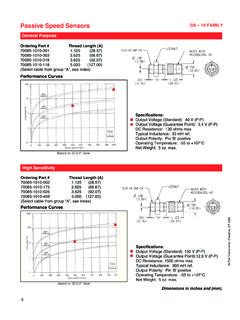
8 Gap. SENSORS with .187 piece are tested with an 8 gear, 100k ohms load; .106 dia. & smaller pole piece sensorsare tested with a 20 gear, 100k ohms load. SENSORS with connectors also use a 250 pf capaci-tor shunted across the 4: sensor output as a functionof gear tooth PieceGear PitchDia. (in)8 12 16 20 24 32 . Dimension of tooth4 Pole piece diametertop surface2. Tooth height5. Air gap3. Space between teeth6. Gear face widthFor maximum control and approximately sinusoidalwaveform, the following conditions should be obtained:(1) equal to or slightly less than (4)(2) equal to or more than (3)(3) approximately to 3 times (4)(5) as small as possible, .005 minimum(6) equal to or more than (4) AI-Tek Instruments , Cheshire, CT USA6 Calculation of Output VoltageSelection of the proper Al-Tek magnetic sensor may require the calculation of sensor output volt-age to assure proper operation in your specific application.
9 To assist in this area, let us consider thefollowing typical application: Requirement is speed display with overspeed and underspeed control aswell as 4-20 mA signal to a PLC. speed range is 0-3600 RPM with low speed set point at 300 RPM,available shaft diameter for mounting a gear is in. and a .030 in. air gap is have selected a Tachtrol 30, P/N T77630-10, with a 60T steel, split gear, P/N G79870-202-1901, andyou are considering to use sensor P/N 70085-1010-001. The question is if the sensor has enoughoutput voltage at 300 can list the following parameters:a. Tachtrol 30: Load impedance - 12k-ohmsSensitivity - 200 mV peakb. Split gear: Outside dia. - in. - 12No. of Teeth - 60c. sensor :Standard output voltage - 40V (P-P) Point - P-P Resistance - 130 ohms inductance - 33 mH ref. Step 1:Calculate surface speed of gear:SS = RPM x Outside Dia. x = 300 x x = 81 IPS6060 Step 2:Determine Peak-to-Peak output voltage:Referring to the performance curves of sensor P/N 70085-1010-001 the min.
10 Output voltageis V (P-P) at 81 IPS and in. gap. It is a fact that output voltage vs. surfacespeed is a near linear function; therefore, another method of determining output voltage isto set up a ratio using the guarantee (P-P)= EE = .55V (P-P)500 IPS 81 Step 3:Correction for pitch:For a in. pole piece dia. and a 12 gear the correction factor from Table A is 1 .41.(See pg. 5)Ec= .55 x = .78 V (P-P)Step 4: Converting to peak voltage: Simply divide by .78 2 = .39V 5:Correction for load:The .39V or 390mV sensor output voltage will be divided across the impedance of the loadand sensor . The load impedance is 12000 ohms resistive. The impedance of the sensor hasa resistive and inductive element. At low frequencies the inductive element is very small andcan therefore be disregarded, leaving the max. DC resistance of 130 ohms for load correction factor (fL)can be expressed as:(fL)= Z (load) = 12000 =.