Transcription of Series 1 Steel - Straight Sections - Cooper Industries
1 Series 1 SteelSeries 1 Steel - Straight SectionsH-1B-Line Series Cable Tray SystemsEatonSeries 1 SteelHowTheServiceAdvisorWorksWe know that your time is important! That s why the color-coding system in this catalog is designed to help youselect products that fit your service needs. Products are marked to indicate the typical lead time for orders of 50pieces or :How do I select my Straight Sections . covers, or fittings so that I get the quickest turnaround?Service Advisor:Each part of our selection chart is shown in colors. If any section of a part number is a differentcolor, the part will typically ship with the longer lead time represented by the Fastest shipped itemsBlack = Normal lead-time itemsRed= Normally long lead-time itemsExample:156G 09 - 24 - 144 Part will have a longlead time because of the 156G the part number from 156G to 156P will change the coding to black for all Sections and reduce lead 1 Steel - Accessories & FittingsH-2B-Line Series Cable Tray SystemsEatonB-Line SeriesNEMA, CSA & UL Span Load Deflection Design Factors Span Load Deflection Design FactorsSIde Rail Dimensions Classificationsftlbs/ftMultiplier for Two Railsmeters kg/mMultiplier for Two RailsNEMA.
2 12A, 8C6204* Area = * = cm2148 CSA: Sx = = cm3UL Cross-Sectional Ix = = cm4 Area: *When using 12" rung spacing load capacity is limited to 195 lbs/ft ( kg/m)for 36" tray width. When cable trays are used in continuous spans, the deflection of the cable tray is reduced by as much as 50%.Design factors: Ix = Moment of Inertia, Sx = section are based on simple beam tests per NEMA VE 1 on 36" wide cable tray with rungs spaced on 12" centers. The publishedload safety factor is To convert safety factor to , multiply the published load by To obtain mid-span deflection, multiply a load by the deflection multiplier. Cable tray must be supported on spans shorter than or equal to the length of the cabletray being installed.
3 Gauge3" NEMA VE 1 Loading DepthActual Loading Depth = " Straight section Part NumberingPrefixExample:148 P 09 - 24 - 144 SeriesMaterialTypeWidthLength148P= Pre-GalvanizedLadder-06= 6" 144= 12 6" rung spacing09= 9" 120 = 10 Hot Dip 09= 9" rung spacing12= 12"Galvanized12= 12" rung spacing18= 18"After Fabrication24= 24"Steel30= 30"Trough-36= 36"6" thru 24" wide04= Vented BottomSB= Non-Ventilated BottomSee page APP-1 for additional rung options. *SB available for all 1 Steel Primary Length. Secondary page C-23 for explanation of Fastest shipped items Black = Normal lead-time items Red= Normally long lead-time itemsLadder Type(Specify Rung Spacing)Ventilated BottomNon-VentilatedSeries 1 Steel - Straight SectionsH-3B-Line Series Cable Tray SystemsEatonOverall Width(Width + 1/8 )Forside rail& rung data,see chart onpages APP-6 & APP-7 RungSpacingValues are based on simple beam tests per NEMA VE 1 on 36" wide cable tray with rungs spaced on 12" centers.
4 Cable trays willsupport without collapse a 200 lb. ( kg)concentrated load over and above the published loads. The published load safety factoris To convert safety factor to , multiply the published load by To obtain mid-span deflection, multiply a load by thedeflection multiplier. Cable tray must be supported on spans shorter than or equal to the length of the cable tray being installed.*When using 12" rung spacing, load capacity is limited to 234 lbs/ft ( kg/m)for 30" tray width and 195 lbs/ft ( )for 36" tray width. When trays are used in continuous spans, the deflection of the tray is reduced by as much as 50%.Design factors: Ix = Moment of Inertia, Sx = section 1 Steel4" NEMA VE 1 Loading DepthActual Loading Depth = "Ladder Type(Specify Rung Spacing)Ventilated BottomNon-VentilatedGreen= Fastest shipped items Black = Normal lead-time items Red= Normally long lead-time itemsSeries 1 Steel - Straight SectionsH-4B-Line Series Cable Tray SystemsEatonStraight section Part NumberingPrefixExample.
5 156 P 09 - 24 - 144 SeriesMaterialTypeWidthLength156P= Pre-GalvanizedLadder-06= 6" 144= 12 6" rung spacing09= 9" 120 = 10 Hot Dip 09= 9" rung spacing12= 12"Galvanized12= 12" rung spacing18= 18"After Fabrication24= 24"Steel30= 30"Trough-36= 36"6" thru 24" wide04= Vented BottomSB= Non-Ventilated BottomSee page APP-1 for additional rung options. *SB available for all widths. Primary Length. Secondary page C-23 for explanation of Width(Width + 1/8 )Forside rail& rung data,see chart onpages APP-6 & APP-7 RungSpacingB-Line SeriesNEMA, CSA & UL Span Load Deflection Design Factors Span Load Deflection Design FactorsSIde Rail Dimensions Classificationsftlbs/ftMultiplier for Two Railsmeters kg/mMultiplier for Two RailsNEMA: 12B, 8C6304* Area = * = cm2156 CSA: Sx = = cm3UL Cross-Sectional Ix = = cm4 Area: gaugeAll dimensions in parentheses are millimeters unless otherwise are based on simple beam tests per NEMA VE 1 on 36" wide cable tray with rungs spaced on 12" centers.
6 Cable trays willsupport without collapse a 200 lb. ( kg)concentrated load over and above published loads. The published load safety factor To convert safety factor to , multiply the published load by To obtain mid-span deflection, multiply a load by thedeflection multiplier. Cable tray must be supported on spans shorter than or equal to the length of the cable tray being installed.*When using 12" rung spacing, the load capacity is limited to 234 lbs/ft ( kg/m)for 30" tray width and 195 lbs/ft ( kg/m)for 36" tray width. When trays are used in continuous spans, the deflection of the tray is reduced by as much as 50%.Design factors: Ix = Moment of Inertia, Sx = section " NEMA VE 1 Loading DepthActual Loading Depth = "Ladder Type(Specify Rung Spacing)Ventilated BottomNon-VentilatedSeries 1 SteelGreen= Fastest shipped items Black = Normal lead-time items Red= Normally long lead-time itemsSeries 1 Steel - Straight SectionsH-5B-Line Series Cable Tray SystemsEatonAll dimensions in parentheses are millimeters unless otherwise section Part NumberingPrefixExample.
7 166 P 09 - 24 - 144 SeriesMaterialTypeWidthLength166P= Pre-GalvanizedLadder-06= 6" 144= 12 6" rung spacing09= 9" 120 = 10 Hot Dip 09= 9" rung spacing12= 12"Galvanized12= 12" rung spacing18= 18"After Fabrication24= 24"Steel30= 30"Trough-36= 36"6" thru 24" wide04= Vented BottomSB= Non-Ventilated BottomSee page APP-1 for additional rung options. *SB available for all widths. Primary Length. Secondary page C-23 for explanation of Width(Width + 1/8 )Forside rail& rung data,see chart onpages APP-6 & APP-7 RungSpacingB-Line SeriesNEMA, CSA & UL Span Load Deflection Design Factors Span Load Deflection Design FactorsSIde Rail Dimensions Classificationsftlbs/ftMultiplier for Two Railsmeters kg/mMultiplier for Two RailsNEMA: 12B, 8C6308* Area = * = cm2166 CSA: Sx = = cm3UL Cross-Sectional Ix = = cm4 Area: gaugeWhen cable trays are used in continuous spans, the deflection of the tray is reduced by as much as 50%.
8 Design factors: Ix = Moment of Inertia, Sx = section are based on simple beam tests per NEMA VE 1 on 36" wide cable tray with rungs spaced on 12" centers. Cable trays willsupport without collapse a 200 lb. ( kg)concentrated load over and above published loads. The published load safety factor To convert safety factor to , multiply published load by To obtain mid-span deflection, multiply a load by the deflection multiplier. Cable tray must be supported on spans shorter than or equal to the length of the cable tray being " NEMA VE 1 Loading DepthActual Loading Depth = "Ladder Type(Specify Rung Spacing)Ventilated BottomNon-VentilatedSeries 1 SteelGreen= Fastest shipped items Black = Normal lead-time items Red= Normally long lead-time itemsAll dimensions in parentheses are millimeters unless otherwise 1 Steel - Straight SectionsH-6B-Line Series Cable Tray SystemsEatonStraight section Part NumberingPrefixExample.
9 176 P 09 - 24 - 144 SeriesMaterialTypeWidthLength176P= Pre-GalvanizedLadder-06= 6" 144= 12 6" rung spacing09= 9" 120 = 10 Hot Dip 09= 9" rung spacing12= 12"Galvanized12= 12" rung spacing18= 18"After Fabrication24= 24"Steel30= 30"Trough-36= 36"6" thru 24" wide04= Vented BottomSB= Non-Ventilated BottomSee page APP-1 for additional rung options. *SB available for all widths. Primary Length. Secondary page C-23 for explanation of Width(Width + 1/8 )Forside rail& rung data,see chart onpages APP-6 & APP-7 RungSpacingB-Line SeriesNEMA, CSA & UL Span Load Deflection Design Factors Span Load Deflection Design FactorsSIde Rail Dimensions Classificationsftlbs/ftMultiplier for Two Railsmeters kg/mMultiplier for Two RailsNEMA: 12B, Area = * = cm2176 CSA: 137 Sx = = cm3UL Cross-Sectional Ix = = cm4 Area.
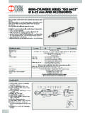
10 GaugeCatalogCable Tray Tray CutWidth 'L'9(*)-803(X)Mitered Thru 36" N/A9(*)-803(X)-12 Not mitered Thru 12" 16"9(*)-803(X)-36 Not mitered Thru 36" 41"9(*)-803(X)-12 or 9(*)-803(X)-36 One pair splice plates with (*)-803(X)Splices onlyLLSeries 1 SteelGGPZNGZNGZNGZNR equires supports within 24 on both sides, per NEMA VE Fastest shipped items Black = Normal lead-time items Red= Normally long lead-time itemsAll dimensions in parentheses are millimeters unless otherwise 1 Steel - AccessoriesH-7B-Line Series Cable Tray SystemsEatonStandard (L-Shaped) Splice Plates One pair including hardware provided with each section .(Expansion splice quantity subtracted) Furnished in pairs with hardware.