Transcription of Series 248 Hydraulic Actuators m - mts.com
1 Series 248 Hydraulic Actuators m Description Options The Series 248 Hydraulic Actuators are The following options are available with heavy-duty, double-ended, linear force the Series 248 Actua tors. Contact MTS. generating Actuators that operate under Systems Corporation for additional Benefits Hydrostatic pressure-centering . pre cision servovalve control in MTS information on these options. bearings for continuous high closed- loop testing systems. The Series Porting speed operation under heavy 248 Actuators are designed specifically Optional porting can be pro vided to . side loaded conditions. for low friction, low distortion, high accommodate flow requirements greater Large-diameter, single-piece, sideload, vibration testing of structures.
2 Than 90 gpm (340 L/min). chrome-plated piston rod and components. provides strength and lateral LVDT. This option provides a piston rod stiffness.. Thick-walled cylinder for overall . displacement feedback signal to the rigidity and high transverse system control electronics. The LVDT. resonant frequency. coil is secured to either the pedestal base, static support, or open housing Displacement transducer is assembly. coax ially mounted within the hollow piston rod for simple Pedestal Base construction, increased accuracy, The pedestal base allows the actuator to . and transducer protection. be mounted to a reaction mass for free- Standard built-in Hydraulic standing vibration testing.
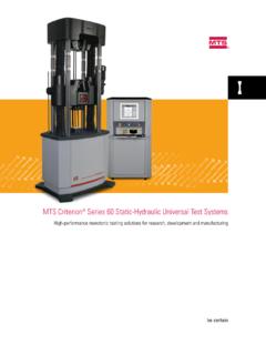
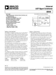
3 Cush ions protect the end caps during full-stroke, high-velocity Static Support Assembly This option is used when it is desirable to operation.. Accepts a wide range of . support a heavy structure or component on the actuator piston rod without using servovalves from 1 to 90 gpm (4. to 340 L/min). Special porting Hydraulic pressure to offset the weight of and cushions are available as the specimen. an option for flow requirements greater than 90 gpm (340 L/min). Optional static support assembly . uses pressurized nitrogen to offset the weight of a heavy specimen or fixture that is used with the actuator . This reduces power requirements on the Hydraulic system. Typical Series 248 Hydraulic actuator assembly shown with optional servovalve, manifold, accumulators, differential pressure cell, and other accessories Design Characteristics Pedestal Base MTS Actuators are manufactured to close Allows the actuator to be mounted to a tolerances to ensure reliability, long life, reaction mass for vibration testing.
4 And complete part interchangeability LVDT. (within a given actuator model). The This assembly provides a signal proportional following characteristics are common to to actuator displacement. The LVDT core all Series 248 Actuators . is secured inside the hol low piston rod Piston Rod End (fixture attachment end) by a core mount. On the pedestal base Has a center position internal thread and and open housing con fig urations, the an internal thread circular hole pattern for core mount can be adjusted to establish a mounting fixtures, vibration tables, wheel zero reference point for the actuator . The pans, load cell, etc. static support configuration has a fixed core mount to provide a mid-stroke zero m Porting reference point.
5 Hydraulic fluid is ported into the actuator through the retraction port or the Static Support (not shown). extension port. The fluid flow is regulated The Series 248 Actuators may be used in by a servovalve. As high Hydraulic pressure a static support configuration when it is m is applied to one port, the other port is desir able to support a heavy specimen or opened to a return line, resulting in actu ator fixture on the piston rod without using rod displacement. Hydraulic pressure to offset the weight of the specimen or the fixture. The static m Piston Rod sup port assembly is mounted to the lower The double-ended piston has equal areas end cap of the actuator . on both sides for balanced performance.
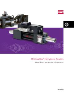
6 It is machined from a single piece of heat- treated alloy steel, hard chrome plated, and precision ground to a fine finish to increase seal and bearing life. The hollow 248 actuator & servovalve (S). piston rod permits convenient installation and accu rate alignment of the LVDT. Piston Seal The close tolerance fit between the piston and cylinder provides an effective viscous seal. Grooves on the piston ensure adequate lubrication of the piston surface during short-stroke, sideloaded tests. Hydrostatic Bearings Each end cap contains four bearing pads which provide a strong centering force to counteract sideloads. Piston Rod Seals One seal assembly is provided in each end cap. This assembly contains a seal which guides excess Hydraulic fluid to the drainback port, and a wiper which prevents external contamination from entering the actuator .
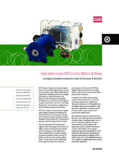
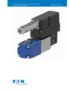
7 Cutaway View of a Typical Series 248 actuator Specifications Specifications for the Series 248 Actuators are list- ed according to actuator model numbers. Other tables list the dimensions for the basic cylinder assembly shown. The open housing and pedestal base configurations are shown on the next page. Piston Rod End 4 holes, "G" thread 8 holes, "G" thread size, "H" deep, size, "H" deep, equally spaced on equally spaced on a "J" diameter. a "J" diameter. Series 248 actuator Specifications "K" thread size "K" thread size, "L" deep "L" deep Model Force Rating Piston Area Rod Diameter Kip kN cm2 in. mm F (dia.). 10 , 16 E (dia.). D 28 (cushion). 38 50 Dynamic Stroke 100 160 D C. 250 (cushion) (min.)
8 Specifications are subject to change without notice. Contact MTS for verification of specifications critical to your needs. A. Basic Cylinder Assembly Dimensions (Stroke Length Dependent). Dynamic B (min.) Stroke A B C D Length in. ( mm). in. mm in. mm in. mm in. mm in. mm in. mm in. mm 1 End Caps (both ends) 2 4 6 M (dia.). 8 10 , Specifications are subject to change without notice. Contact MTS for verification of specifications critical to your needs. 4 holes, "N" thread size, "P" deep, equally spaced on a "Q" diameter. Basic Cylinder Assembly Basic Cylinder Assembly Dimensions (Model Number Dependent). Dimensional Drawing Model E F G H J K in. mm Basic Cylinder 248 in. mm in. mm in.
9 Mm M12 x mm M27 x 2 mm M12 x mm M27 x 2 mm M16 x 2 mm M36 x 3 mm Model L M N P Q in. mm in. mm in. mm in. mm M20 x mm M24 x 3 mm M24 x 3 mm Specifications are subject to change without notice. Contact MTS for verification of specifications critical to your needs. m Open Housing LVDT Dimensions Model A B. 1 in. ( mm) 4 in. ( mm) 8 in. ( mm). and and and 2 in. ( mm) 6 in. ( mm) 10 in. ( mm). Stroke Stroke Stroke in. mm in. mm in. mm in. mm Specifications are subject to change without notice. Contact MTS for verification of specifications critical to your needs. Pedestal Base Dimensions B Model A B C D E F G in. mm in. mm in. mm in. mm in. mm in. mm A in. ( mm). 3/4 -10 UNC-2B in. ( mm) 3/4 -10 UNC-2B 3/4 -10 UNC-2B 3/4 -10 UNC-2B Open Housing LVDT.
10 1 -8 UNC-2B Dimensional Drawing Open House LVDT. 1 -8 UNC-2B 1 -8 UNC-2B 1 -8 UNC-2B .. 1. Applies to Actuators with 1 or 2 in. ( or mm) stroke. 2. Applies to Actuators with 4 or 6 in. ( or mm) stroke. B. 3. Applies to Actuators with 8 or 10 in. ( or mm) stroke. 4. Applies to Actuators with 12 in. ( mm) stroke. 5. Dimension is in. ( mm) for and Actuators with a 1 in. ( mm) or 2 in. ( mm) stroke. A in. ( mm) This dimension and dimension 'B' are one and the same for these models. 4 threaded holes, "E" size, Ordering Information "F" deep, equally spaced on a "G" diameter When ordering a Series 248 actuator , first . Special Porting 8 holes, "C" diameter specify the desired basic cylinder assembly.