Transcription of Series 3, for Closed Circuits Axial Piston, Swashplate ...
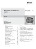
1 RA 92003 Pressure 5800 psiPeak Pressure 6500 psiSize Displacement Pump AA4 VGSeries 3, for Closed CircuitsAxial piston , Swashplate DesignRA92003 AA4VG is a Swashplate design, variable displace-ment Axial piston pump specifically designed forhydrostatic Closed circuit transmissions. The designincorporates a charge pump, charge pressure reliefvalve, two combination high-pressure relief/anti-cavita-tion check valves, and integral Pressure is proportional to drive speed and pump displace-ment and is infinitely adjustable. It increases withincreasing Swashplate angle from zero to its maximumvalue. Swiveling the pump over center smoothlyreverses the direction of oil complete range of modular control and regulatingdevices is pump is available with a full range of through driveoptions and tandem pump : Appendix forSizes 28 and Displacement Pump AA4VG, Series 3RA 92003 CodeHydraulic FluidPetroleum Oil (For operation with other fluids, consult a Rexroth Application Engineer) Axial piston UnitVariable Swashplate design.
2 Nominal pressure 5800 psi; peak pressure 6500 psiAA4 VMode of OperationPump in Closed circuitGSize Displacement Vg max(cm3)2840567190125 180 250 Size 28, see AppendixSize 250, see AppendixControl Options40567190125 180 NoneNVllllllNVHydraulic Control Direct OperatedDGllllllDGElectrical Control ProportionalEPllllllEPElectrical Control Non ProportionalEZllllllEZRotary Manual Servo ControlHWllllllHWHydraulic Control Pilot OperatedHDllllllHDHydraulic Control Speed DependentDAllllllDASolenoid Voltage (EP, EZ, or DA only)12 Volt DCllllll124 Volt DCllllll2 Pressure Cut-OffWith Pressure Cut-OffllllllDNeutral Position Switch (HW control only)Without Neutral Position Switch (no code)llllllOmitWith Neutral Position SwitchllllllLMechanical Stroke LimiterWithout Stroke LimiterllllllOmitWith Stroke LimiterllllllMPorts X3, X4for Stroking PressureWithout Ports X3, X4 (no code)llllllOmitWith Ports X3, X4llllllTRegulating (DA) CartridgeNV EZ DG EP HW HD DA40567190125 180 Without DA Cartridgellllll llllll1 With DA Cartridge, fixed adjustment lllllllllll2 With DA Cartridge, mech.
3 Adjustable w/lever lll lllllll3 With DA Cartridge, fixed adjustment andHydraulic Inching Valve built on lllllll4 With DA Cartridge, mech. adjust. w/lever andHydraulic Inching Valve built on lllllll5 With DA Cartridge, fixed adjustment andconnection for TH7 master controller lllllllllll7 Series 3 Index2 Direction of Rotation(As viewed from drive shaft)clockwiseRcounter-clockwiseL Shaft Option S is standard for the front pump of tandem See Page Request; With Cold Start bypass valve. See page Factory Not AvailableAxial piston UnitOperationDisplacementControl & OptionsRegulating CartridgeDesign SeriesIndexDirection of RotationSealsNBRPNBR, FPM shaft sealNShaft Type (For maximum permissible shaft torque refer to page 33)40567190125 180 Spline SAE (Standard for single pump)llllllSSpline SAE (Standard for tandem pump, 1stpump) ll llTSpline SAE (Only for tandem pump, 2ndpump)l l USpline DIN 5480 (For tandem pump, 2nd pump) m ZMounting Flange40567190125 180 SAE2 boltll C4 bolt lD2 + 4 bolt lll FPort Connections40567190125 180 Ports A & B (SAE 4-bolt flange), on top and bottomllllll52 Charge Pump40567190125 180 With Charge Pump & without Through-DrivellllllF00 Without Charge Pump & without Through-DrivellllllN00 With Charge Pump & with Charge Pump & with 180 ShaftFlangeSAE A(5 8"9T 16/32P)SAE A, B(7 8"13T-16/32P)SAE B, B B(1"15T-16/32P)SAE B, B B(1"15T-16/32P)SAE C, 2-boltl.
4 09 SAE C(11 4"14T-12/24P)SAE C, 2-bolt (N35x2x30x16x9H DIN 5480)SAE D, 2+4-bolt l ..73 SAE D(13 4"13T-8/16P)SAE D, 2+4-bolt D(13 4"13T-8/16P)SAE E, 4-bolt Valves Adjustment Range40567190125 180W/high press. relief valves, pilot oper. psi with bypass llll1 With high pressure relief psi without bypassll 3 Direct operated, fixed settingwith bypassll psi without bypassll 4with bypassll 6 Filtration40567190125 180 Filtration in Charge Pump suction linellllllSCharge Pressure Filtration (Ports Fe and Fa)llllllDCold start valve and ports for external charge circuit filter (Ports Fe and Fa)mmmmm mKMounted Filter (Without contamination indicator) llllllFFilter with visual contamination indicator llllllPFilter with electrical contamination indicator llllllLFilter with visual and electrical contamination indicator llllllMExternal Charge Supply (Units without charge pump N00 or )llllllEAA4V G/ 3 2 52*See Appendix for Sizes 28 and Displacement Pump AA4VG, Series 3RA 92003 AA4VG is a Swashplate design, variable displacement, overcenter, Axial piston pump.
5 It has been designed exclusively forclosed circuit hydrostatic transmissions where a self-containedpump package is required. The pump design incorporates acharge pump, a charge pressure relief valve, two combinationhigh pressure relief and make-up check valves, and an inte-grated pressure cut-off AA4VG pump may be mounted in any position around thehorizontal (drive shaft) axis. Other mounting orientations ( shaft vertical) are possible, but should be reviewed with aRexroth Application Engineer prior to finalizing the design. Thecase drain line should be connected to the highest case drainport (T1or T2) so that the pump case always remains full of case drain piping, or hose, should be sized to accept the fullflow of the charge pump at the maximum anticipated drivespeed, with minimal pressure RecommendationsThe AA4VG pumps are supplied as standard for use with goodquality, petroleum oil based, anti-wear hydraulic fluids.
6 Moredetailed information regarding the selection of hydraulic fluidsand their application limits can be found in our Data SheetsRA 90220 (Petroleum Oil), RE 90221 (Biodegradable Fluids)and RA 90223 (Type HF Fire Resistant/Synthetic Fluids).For applications with biodegradable or Type HF fluids, possiblereduction of the operating specifications may be consult Rexroth and your oil Viscosity RangeIn order to obtain optimum efficiency and service life, we recom-mend that the operating viscosity (at normal loop operatingtemperature) be selected from within the range:Optimum Viscosity ( opt) .. SUS ( mm2/S)Viscosity LimitsMax. Viscosity at startup ( max)..7273 SUS (1600 mm2/S)Min. Viscosity for short duration( min)..42 SUS (5 mm2/S) Operating Temperature LimitsMin. operating F (-25 C)Absolute min. F (-40 C)Max. operating temperature for short F (115 C)Selection DiagramNotes on hydraulic fluid selectionIn order to select the correct fluid, it is necessary to know thenormal operating temperature in the circuit ( Closed loop), whenthe system is operated at the design ambient hydraulic fluid should be selected so that, within the operat-ing temperature range, the fluid viscosity is within the optimumrange opt(see shaded area of the selection diagram).
7 We rec-ommend that the higher viscosity grade is selected in each : At an ambient temperature of X F the Closed circuitfluid temperature is 140 F (60 C). Within the optimum operat-ing viscosity range opt (shaded area), this corresponds to ISOviscosity grades VG 46 or VG 68. VG 68 should be : The leakage oil (case drain oil) temperature is influ-enced by pressure and pump speed and is typically higher thanthe circuit temperature. However, maximum temperature at anypoint in the system must be limited to 239 F (115 C).If it is not possible to comply with the above conditions becauseof extreme operating parameters or high ambient temperaturesplease consult Cleanliness LevelsIn order to ensure proper and reliable operation, the hydraulicfluid must be maintained at a minimum cleanliness level of 18/15(ISO/DIS 4406; SAE J1165). Axial piston pump component lifeis directly affected by the cleanliness of the fluid in the F( C)( C)Cleanliness Recommendations:ClassClassISO/DIS 4406 (SAE J1165)18/1517/14 NAS 163898 SAE, ASTM, AIA65 Operating Pressures RangesMain pump:Nominal charge pressure; bar (290 psi)Nominal pressure (port A or B); bar (5800 psi)Peak pressure (port A or B); bar (6525 psi)Maximum case drain pressure (T1,T2,T3, and T4) bar abs.
8 (30 psia)short term (cold start)..3 bar abs. ( psia)Charge pump:Nominal pressure bar (290 psi)Peak pressure pH bar (580 psi)Min. pressure at charge pump inlet port (S):at = 141 SUS (30 cSt)..p bar abs. ( in-Hg.)at cold bar abs. ( in-Hg.)Viscosity v mm2/s (SUS)16(80)36(170)5 (42)1600 (7425)vopt. VG 22VG 32VG 46VG 68 Temperature t in F ( C)VG 100(-40)(-30)(-20) (-10)(0)(10) (20) (30) (40) (50) (60) (70) (80) (90)(100)(110)-40-20100 120 140020406080160180200 22024016001000600400200100604020105(7000 )(5000)(3000)(2000)(1000)(500)(300)(150) (200)(100)(80)(70)(60)(50)(40)Technical DataRA 92003 Displacement Pump AA4VG, Series 3 Technical DataAA4VG Specifications(Theoretical values; rounded)Size40567190125180 DisplacementVariable pumpVg maxcm3/rev40567190125180in3 pumpVgHcm3 rpm at Vg maxnmax contrpm400036003300305027502400limited max. rpm nmax limit rpm420039003600330031002900intermittent max. rpm nmax Intermrpm500045004100380034503000minimum rpmnminrpm500500500500500500 Flowat nmax contand Vg nmax cont p = 400 barPmaxkW107134156183229288 p = 5800 psihp144180209245307386 Torqueat Vg max p = 400 barMmaxNm2543564515727951144(without charge pump) p = 5800 psilb-ft187263333423586844 p = 100 p = 1450 of inertia (about drive axis) (standard model without through drive) Limited maximum rpm: at half corner power ( at Vg maxand pN/2) Intermittent maximum rpm: at high idle speed during engine overspeed: p = 70 150 bar (1015 2176 psi) and Vg max with reversing loads.
9 P < 300 bar (4350 psi) and t < 5 secondsVg= Displacement (cm3or in3) per revolution p =Differential pressuren =Speed (rpm)Input Drive(Permissible Axial and radial loading on drive shaft)Size40567190125180 Distance of Fq (from shaft shoulder) permissible radial load at distanceaFq permissible Axial load Fq (Fq)a, b, cFaxMany factors influence the selection of a filter to achieve thedesired cleanliness level, including: dirt ingression rate, requiredcleanliness level, and system complexity. We have found thefollowing filter Beta ( ) ratios (ISO 4572) to be satisfactory:Suction 10 & 30 100 Charge Pressure Filtration .. 10 & 20 100 Machine testing is necessary to confirm the ability of theselected filter to maintain the desired fluid cleanliness Flow Suction Filtration (standard model)..SFilter type: ..Filter without bypassFilter element pressure drop:at = 141 SUS (30 cSt); n = p bar ( psi)at =4635 SUS (1000 cSt); n=1000 rpm.
10 P bar ( psi)Min. pressure at charge pump inlet port (S):at = 141 SUS (30 cSt)..p bar abs. ( in-Hg.)at cold bar abs. ( in-Hg.)The filter should be fitted with a P indicator and/or OptionsVariable Displacement Pump AA4VG, Series 3RA 92003 Pressure (Ports Fe & Fa)Filter type:..Filter without bypassFilter element pressure drop (line mounted filter):at =141 SUS (30 cSt); n = p 1 bar ( psi)at cold pmax= 3 bar ( psi)(valid for entire speed range nmin nmax)Please note: With Direct Operated Hydraulic Control Type DG, controlpressure should be supplied from the PSport. The filter should be fitted with a P indicator and/or switch setat 3 bar ( psid). circuit (Ports Fe & Fa) (Ports Fe & Fa)SizeK1K2 Femm (in)mm (in)40112 ( ) ( )3 4"-16 UNF-2B; 15 deep56115 ( ) ( )3 4"-16 UNF-2B; 15 deep71134 ( ) ( )11 16"-12 UN; 20 deep90128 ( ) ( )11 16"-12 UN; 20 deep125147 ( ) ( )15 16"-12 UN-2B; 20 deep180148 ( ) ( )15 16"-12 UN-2B; 20 deepExternal Charge (without charge pump)On units supplied without an integrated charge pump (N00 ) the suction port (S) is plugged, and the external chargesupply is connected at port note that the externally supplied charge flow must bemaintained at the cleanliness levels indicated on page 4.