Transcription of DDC20 Axial Piston Variable Displacement Pump Technical ...
1 Technical Information DDC20 . Axial Piston Variable Displacement Pump Technical Information DDC20 Axial Piston Variable Displacement Pump Revision history Table of revisions Date Changed Rev February 2017 Change charge pump housing 0102. January 2016 Add SAE-A, 13T Auxiliary Pad Option 0101. April 2015 Minor update in Model Code BB. March 2015 Add Implement Pump and SAE A Mounting Flange Options, and Converted to Danfoss BA. layout - DITA CMS. March 2013 Paint and Tag AC. Novemebr 2011 Minor edits AB. October 2011 First edition AA. 2 | Danfoss | February 2017 L1104976 | BC00000191en-US0102. Technical Information DDC20 Axial Piston Variable Displacement Pump Contents General Description Key 5. Typical 5. System Schematic Technical Specifications Design Performance 7. Operating Fluid Operation High Pressure Relief / Check Valve (HPRV).. 9. High pressure relief / check valve with Bypass Charge Pressure Relief Valve (CPRV).
2 11. Loop Flushing 13. Direct Displacement Control Handle 13. Operating Parameters 14. Input System Charge Charge Pump Inlet Case 15. System Design Parameters Filtration System ..17. 18. Suction Charge Pressure 18. External Pressure 18. Independent Braking 19. Fluid Case Charge Charge Pump 20. Charge Pump Output 20. Implement 21. Bearing Loads and Applications with External Shaft 23. Input Shaft Mounting Flange Estimating Overhung Load Understanding and Minimizing System Size 27. Model Code Model Code: A, B, R, C, E, G, 28. Model Code: H, K, Model Code: J, S, 30. Model Code: N, P, Y, Danfoss | February 2017 L1104976 | BC00000191en-US0102 | 3. Technical Information DDC20 Axial Piston Variable Displacement Pump Contents Installation Drawings With Aux-Pad, No Charge Pump, Left Trunnion, SAE A Flange With Aux-Pad, No Charge Pump, Left Trunnion, SAE B Flange 34.
3 With Charge Pump, No Aux-Pad, Left Trunnion, SAE A Flange With Charge Pump, No Aux-Pad, Left Trunnion, SAE B Flange 38. With Implement Pump, No Aux-Pad, Left Trunnion, SAE A Flange 40. With Implement Pump, No Aux-Pad, Left Trunnion, SAE B Flange 42. Input Shafts: AA, BA, 44. Input Shafts: AB, BB, 45. Input Shafts: AC, BC, Auxiliary Mounting 47. Reference Literature 4 | Danfoss | February 2017 L1104976 | BC00000191en-US0102. Technical Information DDC20 Axial Piston Variable Displacement Pump General Description Design The DDC20 is a compact and lightweight Variable Displacement Axial Piston pump intended for use in closed circuit low to medium power applications. DDC20 is a direct Displacement control pump utilizing an advanced slipper Piston design. The flow rate is infinitely Variable between zero and maximum. The direction of flow is commanded by tilting the swashplate in one direction or the other from the neutral (zero flow) position.
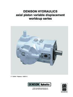
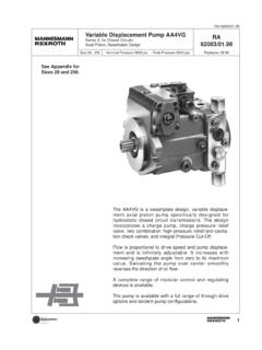
4 Reversing the direction of flow reverses the direction of motor rotation. Key Features Displacement 20 cm3/rev [ in3/rev]. Optional bypass valve and loop flushing valve Optional integral charge pump / Implement pump Compact design with best in class pressure ratings and durability Low noise Backed by a global network of Danfoss service provider Mounting flange (SAE-A / B). Typical Applications Turf Care Greens Mower Zero Turn Radius Mower Loaders Utility Vehicles Compact Agricultural Machinery Small Compactors Compact Construction Equipment DDC20 Cross-Sectional View Trunnion Valve plate Piston Slipper Charge pressure relief valve Ball bearing Input shaft Charge pump Endcap Needle bearing Swashplate Check and high pressure relief valve Bypass valve P400023. Danfoss | February 2017 L1104976 | BC00000191en-US0102 | 5. Technical Information DDC20 Axial Piston Variable Displacement Pump General Description System Diagram Heat exchanger Reservoir bypass Filter Heat exchanger Charge pressure relief valve Cylinder block assembly OMR.
5 Orbital motor Charge pump Bypass valve Output shaft Suction flow Input Variable High pressure relief/ Loop flushing valve Working Loop (Low Pressure) and shaft Displacement check valves Charge Pressure pump Working Loop (High Pressure). Case flow P400024. Schematic Diagram L3 M3 MA. A. B. L1 L2 S MB. P400025. 6 | Danfoss | February 2017 L1104976 | BC00000191en-US0102. Technical Information DDC20 Axial Piston Variable Displacement Pump Technical Specifications Design Specifications Features DDC20 . Axial Piston pump of journal trunnion design with Variable Design Displacement Direction of input rotation Clockwise or counterclockwise Pump installation position is discretionary, however the recommended trunnion position is on the side or at the bottom. Consult Danfoss for application review when install with the trunnion position on the top. Recommended installation position Vertical input shaft installation is acceptable.
6 The housing must always be filled with hydraulic fluid. Recommended mounting for a multiple pump stack is to arrange the highest power flow towards the input source. Consult Danfoss for nonconformance to these guidelines. Filtration configuration Suction or charge pressure filtration Other system requirements Independent braking system, suitable reservoir and heat exchanger Control type Direct Displacement control Performance Specifications Features Units DDC20 . Displacement1 cm3/rev [in3/rev] [ ]. Mass moment of inertia of rotating components kg m2 [slug ft2] [ ]. With charge pump 10 [22]. With implement 11 [ ]. Weight dry kg [lb]. pump With auxiliary pad 12 [ ]. Oil volume Case only liter [US gal] [ ]. ISO3019-1 flange 101-2 (SAE B), 2 bolt Mounting flange ISO3019-1 flange 82-2 (SAE A), 2 bolt ISO 3019-1, outer dia 22mm-4 (SAE B, 13 teeth).
7 Input shaft outer diameter, Splines, key shafts2 ISO 3019-1, outer dia 22mm-1 (Straight Key, Ls). ISO 3019-1, outer dia 22mm-1 (Straight Key, Special length). ISO 3019-1, flange 82 - 2, outer dia 16 mm - 4. Auxiliary mounting flange with metric fasteners, shaft outer (SAE A, 9 teeth). diameter and splines ISO 3019-1, flange 82 - 2, outer dia 19 mm - 4. (SAE A, 11 teeth). Suction ports ISO 11926-1, 7/8 -14 (SAE O-ring boss). ISO 11926-1, 7/8 -14 (SAE O-ring boss) Twin port, Main port configuration radial Case drain ports L1, L2 , L3 ISO 11926-1, 3/4 -16 (SAE O-ring boss). Other ports See Installation Drawings on page 32. Customer interface threads Metric fasteners 1 Max Swashplate angle is 18 degrees. 2 See Installation Drawings on page 32 for mounting flange SAE A. Danfoss | February 2017 L1104976 | BC00000191en-US0102 | 7. Technical Information DDC20 Axial Piston Variable Displacement Pump Technical Specifications Operating Parameters For definitions of the following specifications, see Operating Parameters on page 14.
8 Features Units DDC20 . Minimum for internal charge 500. supply1. Minimum for external Input speed min-1 (rpm) 500. charge supply Rated 4000. Maximum 4500. Maximum working pressure 300 [4350]. Maximum pressure 345 [5004]. System pressure bar [psi]. Minimum low loop (above 4 [58]. case). Charge pressure (minimum) bar@15 lpm [psi/USG] 7 [101]. Minimum (continuous) [6]. Charge pump inlet pressure Minimum (cold start) bar (absolute) [in Hg vacuum] [24]. Maximum Rated [ ]. Case pressure bar [psi]. Maximum 3 [ ]. 1 No load condition. Refer to System Design Parameters/Charge Pump on page 20 for details. Fluid Specifications Features Units DDC20 . intermittent1 5 [42]. Minimum 7 [49]. Viscosity mm2/sec. [ SUS]. Recommended range 12 - 80 [66 - 370]. Maximum (cold start)2 1600 [7500]. Maximum (cold start) -20. Recommended range 60 - 85. Temperature range3 C.
9 Maximum continuous 104. Maximum intermittent 115. Cleanliness per ISO 4406 22/18/13. Efficiency (charge pressure 15-20=75( 10 10). Filtration (recommended filtration) -ratio minimum) Efficiency (suction filtration) 35-45=75( 10 2). Rercommended inlet screen m 100 - 125. mesh size 1 Intermittent=Short term t <1 min per incident and not exceeding 2 % of duty cycle based load-life. 2 Cold start = Short term t < 3 min, p < 50 bar [725 psi], n < 1000 min-1 (rpm). 3 At the hottest point, normally case drain port. 8 | Danfoss | February 2017 L1104976 | BC00000191en-US0102. Technical Information DDC20 Axial Piston Variable Displacement Pump Operation High Pressure Relief / Check Valve (HPRV). The DDC20 is equipped with a combination high pressure relief and charge check valve. The high pressure relief valve (HPRV) function is a dissipative (with heat generation) direct acting pressure control valve for the purpose of limiting excessive system pressures.
10 Each side of the transmission loop has a non-adjustable HPRV valve. When system pressure exceeds the factory setting of the valve, oil flows into the charge gallery. The valve is a differential pressure device working with system and charge pressure. The charge check function acts to replenish the low-side working loop with oil any time the low loop pressure falls below charge pressure. Different pressure relief settings may be used at each system port. The order code specifies HPRV. pressure setting availability. High pressure relief / check valve with orifice A HPRV valve with an orifice is available as an option. In some applications, it is desirable to use a HPRV/. Check with an orifice to allow for easier neutral adjustment. The orifice connects the working loop to the charge gallery. It allows a small amount of loop leakage which expands the dead band around the neutral position of the swashplate.