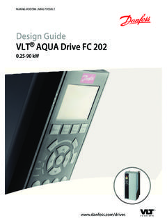
Transcription of VLT AutomationDrive FC 301/302 0.25-75kW - files.danfoss.com
1 MAKING MODERN LIVING POSSIBLED esign GuideVLT AutomationDrive FC 301 Purpose of the Design Additional Abbreviations, Symbols and Document and Software Regulatory CE Low Voltage EMC Machinery UL C-tick Marine Disposal Safety112 Safety Qualified Safety Precautions123 Basic Operating Description of Sequence of Rectifier Intermediate Inverter Brake Load Control Wiring Control FC 301 vs. FC 302 Control Control Structure in VVC+ Control Structure in Flux Sensorless (FC 302 only) Control Structure in Flux with Motor Feedback (FC 302 only)22 ContentsVLT AutomationDrive FC 301/FC 302 Design Guide, kWMG33BF02 - Rev. Speed PID Tuning PID Speed Process PID Advanced PID Internal Current Control in VVC+ Local (Hand On) and Remote (Auto On) Reference Reference Scaling of Preset References and Bus Scaling of Analog and Pulse References and Dead Band Around Zero314 Product Automated Operational Short Circuit Overvoltage Missing Motor Phase Mains Phase Imbalance Switching on the Overload Locked Rotor Automatic Automatic Energy Automatic Switching Frequency Automatic Derating for High Carrier Power Fluctuation Resonance Temperature-controlled EMC Galvanic Isolation of Control Custom Application Automatic Motor Motor Thermal Mains Built-in PID Automatic Flying Full Torque at Reduced Frequency Bypass40 ContentsVLT AutomationDrive FC 301/FC 302 Design Guide, kW2MG33BF02 - Rev.
2 Motor 4 Programmable Dynamic Open Loop Mechanical Brake Closed Loop Mechancial Brake Control/Hoist Mechanical Smart Logic Control (SLC) Safe Torque danfoss VLT FlexConcept 445 System Ambient Operating Temperature and Manual Derating for Running at Low Derating for Low Air Acoustic Vibration and Aggressive Dust Potentially Explosive General Aspects of EMC Test Emission Immunity Motor Motor Bearing Mains Supply The Effect of Harmonics in a Power Distribution Harmonic Limitation Standards and Harmonic Harmonic Galvanic Isolation (PELV) PELV - Protective Extra Low Brake Selection of Brake Resistor55 ContentsVLT AutomationDrive FC 301/FC 302 Design Guide, kWMG33BF02 - Rev. 2013-12-2036 Product Electrical Mains Supply 200-240 Mains Supply 380-500 Mains Supply 525-600 V (FC 302 only) Mains Supply 525-690 V (FC 302 only) General Mains Motor Output and Motor Ambient Cable Control Input/Output and Control Derating for Ambient Derating for Ambient Temperature, Enclosure Type Derating for Ambient Temperature, Enclosure Types Derating for Ambient Temperature, Enclosure Types Measured Values for dU/dt Acoustic Noise817 How to drive Type Ordering Options and Spare Accessory VLT AutomationDrive FC Brake Resistors for FC Other Flat Pack Brake Harmonic Sine-Wave dU/dt Filters1058 Mechanical Mechanical Mechanical Clearance110 ContentsVLT AutomationDrive FC 301/FC 302 Design Guide, kW4MG33BF02 - Rev.
3 Wall Mounting1109 Electrical Tightening Entry Tightening of the Cover after Connections are Mains Fuses and Circuit CE UL Motor Earth Leakage Current Additional Disconnectors and Load Brake PC MCT MCT Harmonic Calculation Software (HCS) Additional Motor Motor Connection of Multiple High Voltage EMC ADN-compliant Installation14210 Application Commonly Used Closed Loop drive Programming of Torque Limit and Programming of Speed Control15011 Options and Communication Options152 ContentsVLT AutomationDrive FC 301/FC 302 Design Guide, kWMG33BF02 - Rev. I/O, Feed-back and Safety VLT General Purpose I/O Module MCB VLT Encoder Option MCB VLT Resolver Option MCB VLT Relay Card MCB VLT Safe PLC Interface Option MCB VLT PTC Thermistor Card MCB VLT Extended Relay Card MCB VLT Sensor Input Option MCB VLT Safe Option MCB VLT C Option Adapter MCF Motion Control Brake Sine-wave dU/dt Common Mode Harmonic IP21/Type 1 Enclosure Remote Mounting Kit for Mounting Bracket for Enclosure Types A5, B1, B2, C1 and C217412 RS-485 Installation and Installation and Network Bus RS-485 Installation and FC Protocol Network FC Protocol Message Framing Content of a Character (byte) Telegram Telegram Length (LGE) Frequency Converter Address (ADR) Data Control Byte (BCC) The Data The PKE Parameter Number (PNU) Index (IND)
4 180 ContentsVLT AutomationDrive FC 301/FC 302 Design Guide, kW6MG33BF02 - Rev. Parameter Value (PWE) Supported Data Process Words (PCD) Writing a Parameter Reading a Parameter Modbus RTU What the User Should Already Modbus RTU Frequency Converter with Modbus Network Modbus RTU Message Framing Frequency Converter with Modbus Modbus RTU Message Start/Stop Address Function Data CRC Check Coil Register How to Control the Frequency Function Codes Supported by Modbus Modbus Exception How to Access Parameter Storage of IND (Index) Text Conversion Parameter danfoss FC Control Control Word According to FC Profile (8-10 Control Profile = FC profile) Status Word According to FC Profile (STW) (8-10 Control Profile = FC profile) Bus Speed Reference Control Word according to PROFI drive Profile (CTW) Status Word according to PROFI drive Profile (STW)
5 192 Index194 ContentsVLT AutomationDrive FC 301/FC 302 Design Guide, kWMG33BF02 - Rev. Purpose of the Design GuideThe Design Guide provides information required forintegration of the frequency converter in a diversity is a registered Additional ResourcesOther resources are available to understand advancedfrequency converter operation, programming, anddirectives compliance. The Operating Instructions provide detailedinformation for the installation and start up ofthe frequency converter. The Programming Guide provides greater detail inhow to work with parameters and manyapplication examples. The VLT Safe Torque Off Operating Instructionsdescribe how to use danfoss frequencyconverters in functional safety applications. Supplemental publications and manuals areavailable from danfoss . See + forlistings. Optional equipment is available that may changesome of the information described in thesepublications.
6 Be sure to see the instructionssupplied with the options for a danfoss supplier or go to foradditional Abbreviations, Symbols andConventionsConventions Numbered lists indicate lists indicate other information and description text indicates cross reference link footnote parameter name, parameter group name,parameter option60 AVM60 Asynchronous Vector ModulationAAmpere/AMPACA lternating current ADAir dischargeAIAnalog InputAMAA utomatic Motor AdaptationAWGA merican wire gauge CDegrees CelsiusCDContant dischargeCMCommon modeCTConstand TorqueDCDirect currentDIDigital InputDMDifferential modeD-TYPED rive DependentEMCE lectro Magnetic CompatibilityETRE lectronic Thermal RelayfJOGM otor frequency when jog function isactivatedfMMotor frequencyfMAXThe maximum output frequency the frequencyconverter applies on its outputfMINThe minimum motor frequency fromfrequency converterfM,NNominal motor frequencyFCFrequency convertergGramHiperface Hiperface is a registered trademark byStegmannhpHorsepowerHTLHTL encoder (10-30 V)
7 Pulses - High-voltageTransistor LogicHzHertzIINVR ated Inverter Output CurrentILIMC urrent limitIM,NNominal motor currentIVLT,MAXThe maximum output currentIVLT,NThe rated output current supplied by thefrequency converterkHzKilohertzLCPL ocal Control PanellsbLeast significant bitmMetermAMilliampereMCMM ille Circular MilMCTM otion Control ToolmHMillihenry InductanceminMinutemsMillisecondmsbMost significant bitIntroductionVLT AutomationDrive FC 301/FC 302 Design Guide, kW8MG33BF02 - Rev. 2013-12-2011 VLTE fficiency of the frequency converter definedas ratio between power output and powerinputnFNanofaradNLCPN umerical Local Control PanelNmNewton MetersnsSynchronous Motor SpeedOn-line/Off-lineParametersChanges to on-line parameters are activatedimmediately after the data value is changedPbr, power of the brake resistor (averagepower during continuous braking)
8 PCBP rinted Circuit BoardPCDP rocess DataPELVP rotective Extra Low VoltagePmFrequency converter nominal output power asHOPM,NNominal motor powerPM motorPermanent Magnet motorProcess PIDThe PID regulator maintains the desired speed,pressure, temperature, ,nomThe nominal resistor value that ensures abrake power on motor shaft of 150/160% for 1minuteRCDR esidual Current DeviceRegenRegenerative terminalsRminMinimum permissible brake resistor value byfrequency converterRMSRoot Mean SquareRPMR evolutions Per MinuteRrecResistor value and resistance of the brakeresistorsSecondSFAVMS tator Flux oriented Asynchronous VectorModulationSTWS tatus WordSMPSS witch Mode Power SupplyTHDT otal Harmonic DistortionTLIMT orque limitTTLTTL encoder (5 V) pulses - Transistor TransistorLogicUM,NNominal motor voltageVVoltsVTVariable TorqueVVC+ Voltage Vector ControlTable AbbreviationsThe following symbols are used in this document:WARNINGI ndicates a potentially hazardous situation which couldresult in death or serious a potentially hazardous situation which couldresult in minor or moderate injury.
9 It may also be usedto alert against unsafe important information, including situations thatmay result in damage to equipment or DefinitionsCoastThe motor shaft is in free mode. No torque on motor. Brake ResistorThe brake resistor is a module capable of absorbing thebrake power generated in regenerative braking. Thisregenerative braking power increases the intermediatecircuit voltage and a brake chopper ensures that thepower is transmitted to the brake resistor. CT CharacteristicsConstant torque characteristics used for all applicationssuch as conveyor belts, displacement pumps and initialising is carried out (14-22 Operation Mode), thefrequency converter returns to the default Duty CycleAn intermittent duty rating refers to a sequence of dutycycles. Each cycle consists of an on-load and an off-loadperiod. The operation can be either periodic duty or non-periodic parameter settings in 4 set-ups.
10 Change between the4 parameter set-ups and edit one set-up, while anotherset-up is CompensationThe frequency converter compensates for the motor slipby giving the frequency a supplement that follows themeasured motor load keeping the motor speed Logic Control (SLC)The SLC is a sequence of user defined actions executedwhen the associated user defined events are evaluated astrue by the Smart Logic Controller. (Parameter group 13-**Smart Standard BusIncludes RS-485 bus with FC protocol or MC protocol. See8-30 A temperature-dependent resistor placed where thetemperature is to be monitored (frequency converter ormotor).IntroductionVLT AutomationDrive FC 301/FC 302 Design Guide, kWMG33BF02 - Rev. 2013-12-20911 TripA state entered in fault situations, if the frequencyconverter is subject to an overtemperature or when thefrequency converter is protecting the motor, process ormechanism.)
