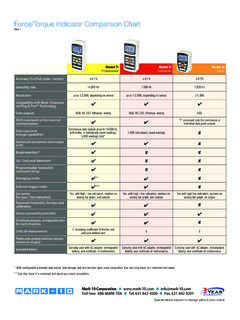
Transcription of Series EG - Mark-10 Force Measurement
1 Series EG DIGITAL Force GAUGES user s guide Thank you! Thank you for purchasing a Mark-10 Series EG Digital Force Gauge. We are confident that you will get many years of great service from this product. Mark-10 digital Force gauges are designed to be easy to use and ruggedly constructed for many years of service in laboratory and industrial environments. This user 's guide provides setup, operating, and programming instructions. Dimensions and specifications are also provided. For additional information or answers to your application questions, contact us and our technical support and engineering teams will be eager to help you. Thank you again for your purchase and happy testing!
2 TABLE OF CONTENTS GENERAL .. 3 RS-232 .. 3 Orientation .. 3 Mounting .. 4 POWER .. 5 CONFIGURATION .. 5 RS-232 .. 5 Mitutoyo BCD .. 6 Automatic Shutoff .. 6 Initial (default settings) .. 6 Calibration .. 6 OUTPUTS .. 6 RS-232 .. 6 Mitutoyo BCD .. 7 Analog .. 7 I/O connector pin diagram .. 7 CALIBRATION .. 7 SPECIFICATIONS .. 8 Capacity x graduation .. 8 Dimensions .. 9 WARRANTY .. 9 Series EG Digital Force Gauge user s guide 3 1 GENERAL Controls Six keys on the front panel are used for all functions and control of the instrument. Some have more than one function, depending on the mode of operation. The main functions are labeled above the keys and the secondary functions are below the keys in smaller type.
3 In the list below the secondary functions are in parenthesis. For detailed descriptions of the secondary functions see Sections 3 and 5. POWER (ENTER) Turns power on and off. UNITS Selects units of Measurement . ZERO Zeroes any tare value (up to the full capacity of the instrument) and clears the peak readings. DATA Initiates a data transmission sequence (if equipped with the communication option). MODE (ADVANCE) Switches the display between normal and peak modes of operation.
4 CLEAR (ESCAPE) Clears peak readings from memory. Orientation In order to accommodate a variety of testing requirements, the orientation of the loading shaft may be set up in either of the two positions shown below. In order to change the loading shaft orientation, simply unscrew the four screws on the back side of the housing, separate the two housing hal ves, rotate one half 180 and reassemble. Upright orientation (as supplied) Alternate orientation (for stand mounting, etc.) Loading shaft Loading shaft EGSERIESSERIESEGZEROPOWERUNITSCLEARESCAP EDATAMODEADVANCEADVANCEMODEUNITSDATAPOWE RESCAPECLEARZEROS eries EG Digital Force Gauge 4 Mounting Gauge shown mounted on Model TSC test stand Recommended use of a dowel pin SERIESEG [ ]BOTTOM PLATEMOUNTING PLATEDOWEL PIN [ ] user s guide 5 2 POWER The gauge is powered by a NiCd rechargeable battery.
5 Since batteries are subject to self-discharge, it may be necessary to recharge the unit after a prolonged period of storage. Plug the accompanying charger into the AC outlet and insert the charger plug into the receptacle on the gauge. The gauge may be operated for 8-10 hours after approximately 16-18 hours of charging. Do not use chargers other than supplied or instrument damage may occur. There are three levels of low battery voltage indication. At the first level the display shows a steady "LO BAT" indicating approximately one hour of charge remaining. The second level is indicated by a flashing "LO BAT". At the third level the whole display except the "LO BAT" indicator will flash for three seconds after which time the gauge will turn itself off.
6 This prevents the instrument from working at voltages too low for reliable operation. 3 CONFIGURATION The Series EG gauges have several features with programmable options allowing many user -specified choices. In order to get to the configuration menu, perform the following: 1. Turn off the gauge. 2. Press and hold MODE. 3. Turn on the gauge. 4. Release MODE. The version number of the internal software will be displayed for a short time followed by either 'AoFF' for a standard gauge or '232' if the communication option has been installed. The following secondary functions of keys are used during the configuration process. ADVANCE Used to step through menu choices. ENTER Used to select a menu choice.
7 ESCAPE Used to quit any function (no change). The following list shows all configuration options. Italics indicate factory settings. 232 - RS-232 settings sub-menu 232d Output Disabled 232E Output Enabled 300 300 baud 600 600 baud 1200 1200 baud 2400 2400 baud 4800 4800 baud Series EG Digital Force Gauge 6 9600 9600 baud 7-1E 7 data bits, 1 stop bit, even parity 7-1o 7 data bits, 1 stop bit, odd parity 7-2E 7 data bits, 2 stop bits, even parity 7-2o 7 data bits, 2 stop bits, odd parity 7-2n 7 data bits, 2 stop bits, no parity 8-1E 8 data bits, 1 stop bit, even parity 8-1o 8 data bits, 1 stop bit, odd parity 8-1n 8 data bits, 1 stop bit, no parity 8-2n 8 data bits, 2 stop bits, no parity Ft F Full data (numeric + units)
8 Ft n Numeric data only bcd - Mitutoyo BCD settings sub-menu bcdd Output disabled bcdE Output enabled nPOL No polarity (absolute value) POL Data with polarity (+ comp., - tension) AoFF - Automatic shutoff settings sub-menu no Disabled 1 1-minute automatic shutoff 5 5-minute " " 10 10-minute " " 20 20-minute " " 30 30-minute " " init - Initial (default) settings sub-menu LB Pounds as default units KG Kilograms" " N Newtons " " TC Real time display at turn on PEAK T Peak tension display at turn on PEAK C Peak compression display at turn on CAL - Calibration sub-menu. See Section 5 user s guide 7 4 OUTPUTS Outputs are available as part of the communication option.
9 If installed, it offers RS-232, Mitutoyo BCD and analog outputs on the 9-pin male connector. Please refer to the pin diagram at the end of this section for proper connection. RS-232 The data transmission can be initiated by pressing the DATA key or by an external device by sending ASCII "?" to the gauge. The gauge will respond by sending the current reading in either full or numeric format, depending on the configuration setting (see Section 3). Polarity sign indicates tensile (-) or compressive (+) forces. The transmitted string has the following format: [POLARITY (SPACE OR -)][DATA][SPACE][UNITS (IF ENABLED)][CRLF] Mitutoyo BCD This output is useful for connection to data collectors, printers, multiplexers or any other device capable of accepting Mitutoyo BCD data.
10 The transmission is initiated by the DATA key (see Section 3 about settings) or by the receiving device. Analog This output can be used for chart recorders, oscilloscopes, data acquisition systems, etc. The output produces 1 volt at full scale of the instrument. The polarity of the signal is positive for compression and negative for tension. I/O connector pin diagram 1 RS-232 receive Input 2 RS-232 transmit Output 3 Mitutoyo request Input 4 Mitutoyo clock Output 5 Signal ground --- 6 Analog Signal Output 7 +12V DC Output 8 Mitutoyo ready Output 9 Mitutoyo data Output 7DB-9P61298345 Series EG Digital Force Gauge 8 5 CALIBRATION Mount the gauge firmly with the loading shaft pointing downward.