Transcription of Series PVP Hydraulics Variable Volume, Piston Pumps
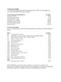
1 Series PVPV ariable volume , Piston PumpsCatalog 2600-102/USAH ydraulicsParker Hannifin CorporationHydraulic Pump/Motor DivisionOtsego, MI 49078 Variable volume Piston PumpsHydraulics1 Quick Reference Data ChartDisplacementPump Delivery *Approx. Noise Levels dB(A)Horsepower AtOperatingPressurePumpcc/rev@ 300 PSI (21 bar) @ Full Flow 1800 RPM (1200 RPM)1800 RPM, (RPM)PSI (bar)Model(In3/rev)in GPM (LPM)500 PSI1000 PSI2000 PSI3000 PSI3600 PSI Displacement &(Maximum)Continuous1200 RPM 1800 RPM(34 bar) (69 bar)(138 bar)(207 bar)(248 bar) 3600 PSI(Maximum)PVP16 16 (.98) ( ) ( ) 74 (69) 75 (70) 77 (75) 80 (75) 68 (64) 3000 3600 (248)PVP23 23( ) ( ) ( ) 74 (69) 75 (70) 77 (75) 80 (75) 68 (63) 3000 3600 (248)PVP33 33( ) ( ) ( ) 74 (69) 75 (70) 77 (75) 80 (75) 69 (65) 3000 3600 (248)PVP41 41( ) ( ) ( ) 72 (67) 70 (67) 73 (68) 74 (71) 71 (71) 2800 3600 (248)PVP48 48( ) ( ) ( ) 74 (68) 72 (67) 77 (69) 78 (72) 73 (73) 2400 3600 (248)PVP60 60( )
2 ( ) ( ) 72 (68) 73 (69) 75 (70) 77 (70) 77 (70) 2200 3600 (248)PVP76 76( ) ( ) ( ) 75 (70) 75 (69) 75 (70) 77 (70) 78 (72) 2200 3600 (248)*Since many variables such as mounting, tank style, plant layout, etc., effect noise levels, it cannot be assumed that the above readings will be equal tothose in the field. The above values are for guidance in selecting the proper pump. Noise levels are A-weighted, mean sound pressure levels at 1 meterfrom the pump, measured and recorded in accordance with applicable ISO and NFPA Series PVPP arker Hannifin CorporationHydraulic Pump/Motor DivisionOtsego, MI 49078 Variable volume Piston PumpsHydraulics2 IntroductionSeries PVPF eatures High Strength Cast-Iron Housing Fast Response Times Two Piece Housing For Ease of Service Metric Pilot, Shaft and Ports Available Replaceable Bronze Clad Port Plate Thru-Shaft Capability Low Noise Levels Replaceable Piston Slipper PlateControls Pressure Compensation Load Sensing Horsepower Limiting Horsepower and Load Sensing Remote Pressure Compensation Adjustable Maximum volume Stop Hi/Lo Torque (Horsepower)
3 Limiting(PVP 41/48, 60/76 Only) Low Pressure StandbySERVOPISTONINLETPORTOUTLETPORTCOM PENSATORSPOOLPUMPHOUSINGCASEDRAINBIASSPR INGSHAFTBEARINGSHAFTSEALREARCOVERSWASHPL ATECYLINDERBARRELPORTPLATESHAFTBEARINGP arker Hannifin CorporationHydraulic Pump/Motor DivisionOtsego, MI 49078 Variable volume Piston PumpsHydraulicsControl OptionsSeries PVP3 General DescriptionAll control is achieved by the proper positioning ofthe swash plate. This is achieved by a servo pistonacting on one end of the swash plate working againstthe combined effect of the off-setting forces of thepistons and centering spring on the other end. Thecontrol spool acts as a metering valve which variesthe pressure behind the servo shown in Figure 1, the amount of flow producedby the Parker Piston Pump is dependent upon thelength of stroke of the pumping pistons.
4 This length ofstroke, in turn, is determined by the position of theswash plate. Maximum flow is achieved at an angleof 15-17 degrees. The rotating barrel, driven by theprime mover, moves the pistons in a circular path andthe Piston slippers are supported hydrostaticallyagainst the face of the swash plate. When the swashplate is in a vertical position, perpendicular to thecenterline of the Piston barrel, there is no Piston strokeand consequently no fluid displacement. When theswash plate is positioned at an angle, the pistons areforced in and out of the barrel and fluid displacementtakes place. The greater the angle of the swash plate,the greater the Piston 1 SERVO PISTONINLETOUTLETPISTONCYLINDERBARRELSWA SHPLATEBIASSPRING DRIVESHAFTP arker Hannifin CorporationHydraulic Pump/Motor DivisionOtsego, MI 49078 Variable volume Piston PumpsHydraulicsControl OptionsSeries PVP4 Pressure Compensated ControlThe swash plate angle controls the output flow of thepump.
5 Swash plate angle is generated by the hydraulicforce of the pumping pistons and the mechanical forceof the swash plate bias of the pump s outlet flow is obtained by over-riding the force of the pumping pistons and bias springwith the hydraulic force of the servo Piston by meansof internal porting. Pressure is connected from theoutlet port to the servo Piston via a compensator compensator spool is held against the springguide by the outlet pressure. When the outlet pressurereaches the setting of the compensator control, thecompensator spool moves, allowing outlet pressureoil to be metered into the servo Piston . This meteredoil provides adequate force to power the servo pistonand override and swash plate forces. The outletpressure causes the servo Piston to move whichreduces the angle of the swash plate and therebyreduces the pump s output flow.
6 When flow is againdemanded by the system, the outlet pressure willmomentarily fall allowing the compensator spool tomove. This movement closes off the outlet pressureto the servo Piston and vents the servo Piston to result of this venting allows the swash plate forcesto move the swash plate angle to maximumdisplacement, thus responding to the demand foradditional flow. Note that the compensator springchamber is vented to the pump case via a hole internalto the compensator 2 SERVO PISTONINLETPORTOUTLETPORTPISTONCOMPENSAT ORSPOOLP arker Hannifin CorporationHydraulic Pump/Motor DivisionOtsego, MI 49078 Variable volume Piston PumpsHydraulicsRemote Pressure Control (M)The pump swash plate actuation is identical to thestandard pressure compensator but can be controlledvia a remote pressure control of the pump output pressure canbe achieved by controlling the pressure at port A,Figure 3 on the compensator.
7 Flow is metered throughthe orifice in the spool from outlet pressure into thespring chamber. The spring chamber pressure islimited by an external relief connected to port A. Thecontrolled pressure at port A is sensed at thedifferential spring chamber. The compensator spoolwill move to the right when the pump outlet pressurereaches a force equal to the differential spring settingplus the controlled port pressure setting. When thespool moves to the right, outlet pressure oil is meteredto the servo Piston and the pump swash plate angleis controlled accordingly. With this option the pumpoutlet pressure can be controlled and varied from aremote control also incorporates a pressure limitingfeature preset at the factory. When the pressure in thedifferential spring chamber reaches the maximum reliefsetting, the dart unseats allowing the spring chamberto vent to the pump case and limits the maximumpressure 3 Control OptionsSeries PVP5 SERVO PISTONINLETPORTOUTLETPORTPISTONORIFICERE MOTE PORTMAX.
8 PRESSUREADJUSTMENT DIFFERENTIALSPRINGP arker Hannifin CorporationHydraulic Pump/Motor DivisionOtsego, MI 49078 Variable volume Piston PumpsHydraulicsFlow Control (Load Sensing) (A)Figure 4 shows a PVP pump with flow control. Thecontrol is identical to the remote pressurecompensation control except for an integral orifice, asolid compensator spool and adjustable differentialpressure control. Port A is connected downstream ofan orifice ( Variable or fixed) to sense the actual workingpressure required. This pressure plus the differentialspring force act on the right side of the compensatorFIGURE 4spool and will urge the spool to the left until outputpressure acting on the left side of the spool balancesthe forces. As the load increases, output pressurewill increase and maintain a constant differentialpressure across the orifice and thus a constant pressure is limited by the internal dart setting is adjustable up to the maximum presetat the OptionsSeries PVP6 SERVO PISTONINLETPORTOUTLETPORTPISTONORIFICEPO RT A MAX.
9 PRESSUREADJUSTMENT DIFFERENTIALSPRINGCHAMBERDIFFERENTIALADJ USTMENTCOMPENSATORSPOOLSYSTEM PRESSUREVARIABLE ORFIXED ORIFICESIGNAL LINEP arker Hannifin CorporationHydraulic Pump/Motor DivisionOtsego, MI 49078 Variable volume Piston PumpsHydraulicsPressure & Horsepower Control (H)This control option is a Torque Limiting Control, butfor constant speed applications it is generally referredto as a Horsepower Control. This control works inconjunction with the Remote Pressure Compensator,control option M . A second pressure control devicecalled a horsepower control block, is assembled tothe main pump housing. The HP block is plumbed toone of the ports on the remote compensator via steeltubing. The control dart in the HP block and themaximum pressure compensator dart in the remotecompensator are connected in parallel.
10 What makesthe control dart in the HP block different from anyother external relief valve is the pressure setting ismechanically linked to the pump swashplate cracking pressure of the HP dart is generallylower than the cracking pressure of the remoteFIGURE 5 Control OptionsSeries PVP7compensator dart. When the HP dart opens thepressure in the differential spring cavity is loweredallowing the compensator spool to meter systempressure in the servo Piston . As the servo pistonextends, it rotates the swashplate and in turn rotatesthe HP cam. As the cam rotates it increases the forceon the HP dart control spring. As the system pressureis allowed to increase, the pump gradually reducesits stroke (flow). When the system pressure reachesthe setting of the maximum pressure dart the normalaction of the remote compensator takes over.