Transcription of Service Bulletin Bulletin No.: 19-NA-180 Date: September, 2019
1 Copyright 2019 General Motors LLC. All Rights BulletinBulletin No.: 19-NA-180 Date: September, 2019 INFORMATIONS ubject: Duramax Diesel New Engine FeaturesBrand:Model:Model Year:VIN:Engine:Transmission:From:To:Fro m:To:ChevroletGMCS ilverado1500 Sierra 15002020 Duramax Diesel, ,Inline6-Cylinder, CRI,DOHC,Turbocharged,VGT,Aluminum,CSS50 V RPO LM210L80,10-SpeedAutomatic,ATSS, CPA,GEN 2 RPO MQBI nvolved CountriesUnited States, Canada, Mexico, South America and Middle EastOverviewBulletin PurposeThe purpose of this Bulletin is to introduce theDuramax diesel turbocharged engine.
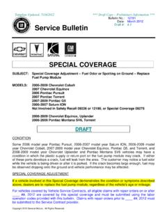
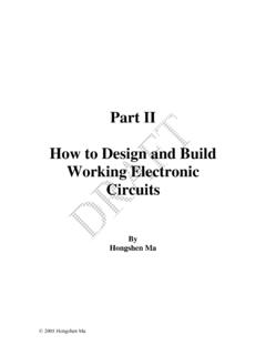
2 Thisbulletin will help the Service Department Personnelbecome familiar with the engine, components, fuelsystem, engine oil requirements, exhaustaftertreatment system and Diesel L6 TurbochargedEngine RPO LM2 OverviewThe Duramax Diesel will be paired with GM s10-speed automatic transmission RPO MQB and willproduce approximately 282 horsepower ( kW)and 450 lb ft ( Nm) of 2 September, 2019 Bulletin No.: 19-NA-1805336795 Left FrontBulletin No.: 19-NA-180 September, 2019 Page 35336810 Right FrontEngine Specifications ( mm) Compression:261 PSI (1800 kPa) Compression Ratio:15:1 Firing Order:1 5 3 6 2 4 Glow Plug V ( mm)Engine Component Description Camshaft:Two camshafts are used, one for allintake valves, the other for all exhaust valves.
3 Thecamshafts are driven by two camshaft sprocketswhich in turn are driven by the secondary timingchain. Compressor Air Intake Turbocharger:Theturbocharger is a variable nozzle design with anelectric vane actuator attached to the exhaustmanifold. The turbocharger supplies compressedair from the turbine/impeller to the engine toincrease power. It also results in higher fuelefficiency and lower CO2 emissions. Crankshaft:The crankshaft is forged steel with4 counterweights. It is supported by 7 mainjournals with main bearings which have oilclearance for lubricating.
4 The thrust bearing islocated at the 6th main journal. A crankshaft pulleyis used to control torsional vibration. The sprocketfor the primary drive chain is machined directly onthe crankshaft. An oil pump sprocket is integratedon to the crankshaft along with a timingreluctor ring. Cylinder Head:The cylinder head is dualover-head camshaft (DOHC) with 4 valves percylinder. The cylinder head is made of castaluminum. Engine Block:The engine block is castaluminum with 6 pressed in iron sleeves. Theblock has 7 crankshaft main bearings with onethrust bearing set.
5 Exhaust Manifold:The exhaust manifold islocated on the cylinder head. It is designed toendure high pressure and high temperature. Theturbocharger is mounted on the exhaust manifold. High Pressure Diesel Fuel Injection System:The high pressure fuel pump supplies pressurizedfuel through the high pressure fuel lines to the fuelrail and then through the fuel injector lines to thefuel injectors. Excess fuel returns to the fuel tankthrough the fuel return pipes. Hydraulic Valve Lash Adjuster:The valve trainuses a valve rocker arm acted on by a hydraulicvalve lash adjuster which reduces friction 4 September, 2019 Bulletin No.
6 : 19-NA-180 Intake Manifold:Intake air flow from the throttlebody passes through the intake manifold to thecylinder combustion chambers. The intakemanifold is made of a composite material. Lower Crankcase Extension:The lowercrankcase extension bolts to the engine block andcontains the oil pump. The oil pump is fasteneddirectly to the lower crankcase extension. The oilpump is a variable vane pump driven by a wettiming belt, which is driven by the oil pumpsprocket. Lower Oil Pan:The lower oil pan is made ofdual-layer stamped aluminum and is attached atthe lower crankcase extension.
7 Positive Crankcase Ventilation System:Thepositive crankcase ventilation (PCV) valve carriesblow-by gas to the turbocharger inlet of the intakesystem. The amount of blow-by gas variesaccording to engine conditions, driving conditionsand the pressure of the turbocharger. The PCVvalve is designed to control the amount ofblow-by gas. Valves:There are 2 intake and 2 exhaust valvesper SystemOverviewThe Duramax utilizes GM s advanced coolingsystem strategy known as Active Thermal Management(ATM). ATM distributes coolant through the engine in atargeted manner, sending heat where it s needed towarm up the engine, thereby reducing friction.
8 Itpromotes quicker heating of the passengercompartment as needed and engine cooling whenneeded during high power operation. The system usesa conventional engine-driven coolant pump. The ECMcontrols the complete ATM system using feedback fromvarious engine has numerous engine coolant temperature(ECT) sensors placed at specific locations throughoutthe cooling system as follows: Engine Block Coolant Temperature Sensor Engine Cylinder Head Coolant Temperature Sensor Engine Inlet Coolant Temperature Sensor Engine Outlet Coolant Temperature Sensor Radiator Outlet Coolant Temperature Sensor Heater Core Inlet Coolant Temperature Sensor Heater Core Outlet Coolant Temperature SensorAdditional sensors used by the ECM to control the ATMsystem are: Engine Oil Temperature Sensor 1 and Sensor 2 Transmission Oil Temperature Sensor Control Valve SensorsBulletin No.
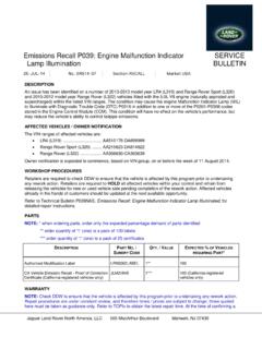
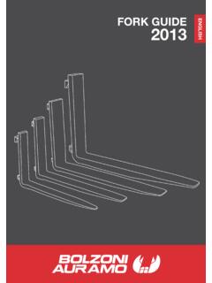
9 : 19-NA-180 September, 2019 Page 5 Engine Coolant Flow Control Valve5340159 The Engine Coolant Flow Control Valve assembly isattached to the engine under the intake manifold. Theengine coolant flow control valve is comprised of twoactuators, the Block Rotary Valve (BRV) (1) and theMain Rotary Valve (MRV) (2). The engine coolant flowcontrol valve consists of two chambers. The firstchamber controls the coolant flow rate across theradiator and bypass. The second chamber controls theflow to the transmission and engine oil cooler, providingheated coolant from the EGR/Turbocharger returncircuit or cold coolant directly from the pump outlet, asrequired based on feedback from the various coolanttemperature sensors.
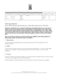
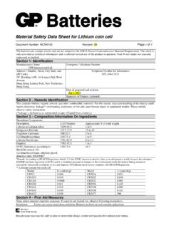
10 The engine coolant flow controlvalve also has an integrated Flow Control Valve (FCV)(3) that limits engine coolant flow from the mechanicalwater pump when full output is not needed. TheExhaust Gas Recirculation (EGR) feed port isalways Coolant Flow Control Valve Reverse View53545881. Block Port2. Head PortPage 6 September, 2019 Bulletin No.: 19-NA-180 Auxiliary Electric Engine Coolant Pump5340434 When the Stop/Start System has shut down the engine,and the ambient temperature is colder than 59 F(15 C), the ECM will activate the Stop/Start relay for theauxiliary electric engine coolant pump motor (1) to turnit ON.