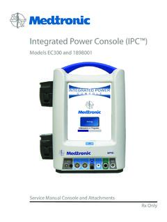
Transcription of Service Manual - Kebomed
1 Service ManualInstructions For UseNIM-Response ??Step 1 of 2 Step 1 of 25/1/2009 9:00 AM5/1/2009 9:00 AM* indicates default settings have been changed* indicates default settings have been changed1. Select Procedure1. Select Procedure GlobalSettingsGlobalSettingsHelpHelpCust om ProceduresCustom ProceduresPeripheralPeripheralNeuro/Otol ogyNeuro/OtologyHead/NeckHead/NeckReport sReportsMonitoringMonitoringSetupSetupNI M-Response IM-Response IM-Response GUI DSP ??Step 1 of 2 Step 1 of 25/1/2009 9:00 AM5/1/2009 9:00 AM* indicates default settings have been changed* indicates default settings have been changed1.
2 Select Procedure1. Select Procedure GlobalSettingsGlobalSettingsHelpHelpCust om ProceduresCustom ProceduresPeripheralPeripheralNeuro/Otol ogyNeuro/OtologyHead/NeckHead/NeckReport sReportsMonitoringMonitoringSetupSetupNI M-Neuro IM-Neuro IM-Neuro GUI DSP Xomed, Inc. 6743 Southpoint Drive NorthJacksonville, FL 32216 Line(800)-874-5797 are trademarks and are registered marks of Medtronic Xomed, information contained in this document was accurate at time of publication. Medtronic reserves the right to make changes in the product described in this Manual without notice and without incorporating those changes in any products already ManualSymbolsTable Of ContentsSymbols.
3 3 Table Of Contents ..3 Buttons and Indicators ..4 System Description ..5 Device Description ..5 Indications for Use ..5 Contraindications ..5 Customer Care ..6 Medtronic Xomed, Inc..6 Help Line ..6 International Service ..6 Introduction ..6 Components ..6 Front Panel ..6 Side Panel ..6 Rear Panel ..6 NIM Patient Interface ..7 Stimulator Probes and Handles ..7 Monopolar ..7 Simulator ..7 Patient Interface and Simulator ..7 Simulator Set-up: ..8 Annual System Quick Check ..8 Power Up Diagnostics ..8 Confirming Electrodes ..9 Electrode Lead Off.
4 9 Stimulation ..9 Mechanical Stimulation ..9 Set and Measure ..10 Threshold Test ..10 Simulation Troubleshooting ..10 Annual System Quick Check Data Sheet ..11 Preventive and Corrective Maintenance ..11 Advanced System Check ..12 Cleaning and Maintenance ..12 Cleaning (after each use) ..12 Storage ..12 Maintenance ..12 Fuses ..13 Console Fuse Replacement ..13 Patient Interface Fuse Replacement ..14 Troubleshooting ..15 Technical Specifications ..17 Block Diagram ..19 Definitions (used in this Manual )APS Automatic Periodic Nerve Integrity NIM-Neuro or the NIM-Response Sequence A sequence is defined as a series of events separated from each other by less than one RejectionPeriod Adjustable delay reading EMG after stimulation.
5 In previous versions of the NIM , this was referred to as Stimulus Artifact or Artifact D e l User Signal Auditory Brainstem SomatosensorySymbolsSerial NumberDo not dispose of this product in the unsorted municipal waste stream. Dispose of this product according to local regulations. See for instructions on proper disposal of this Not Use If Package Is Open Or ContentsUse By DateDo Not ReuseLot NumberFuseAccessoryCatalog NumberAC PowerOutputIs Approximately Equal ToSterilized By Radiation. Do Not Use If Package Is Open Or By Ethylene Oxide.
6 Do Not Use If Package Is Open Or Representative In The European Device Complies With Medical Device Directive 93/42/EECC aution: Federal Law ( ) Restricts This Device To Sale By Or On The Order Of A Physician. QuantityManufacturerDate Of Manufacture4 Service ManualButtons and Indicators ROHS - Environmental Friendly Use Period - China (SJ/T11364-2006).Conforms To IEC/EN60601-1 Certified To CSA EarthEquipotentialConsult Instructions For UseAttention See Instructions For UseProtected Against Vertical Water Against The Effects Of Temporary Immersion In For Water Ingress (IEC 60529)Type BF Applied PartManual Start/StopRf Transmitter (Interference May Occur).
7 Snapshot Option - Open Comments Dialog Option - Send Snapshot to a Printer is Option - Send Snapshot to USB Storage a USB Storage Device is and Indicators In this section all buttons used on the Touch Screen User Interface are displayed with an explanation of how they work. Radio Button: Deselected For option selection where choice is limited to one of two or more Button: SelectedCheck Box: Deselected For option selection where choice is to enable or disable a single or multiple Box: SelectedEMG Audio and Event Tones Check Boxes: One or both must be selected.
8 Both cannot be X: Indicates a failed Check: Indicates a successfully passed Check: Indicates an Active Button: Option Button See associated text indicating Button: Opens Help Screen for Electrode Placement & Sound SamplesIncrease Button: Increases value/SettingDecrease Button: Decreases value/SettingMonitor Button: Opens Monitoring ScreenMeasure Button: To view details of the event Settings Button Opens: Audio, Monitoring, Stimulation, Microscope, and APS Button: Opens panel for adjusting amplitude and time Button: Sends selected information to USB mass storage Button: Used in Reports Section to print reportsFreeze Button: Freezes entire screen (all channels)Snapshot Button: Saves current screen to memory or to selected peripheral Button: Activates STIM 2 stimulus adjustment Button: Initiates an APS baseline acquisition sequenceElectrode Check Button: Opens Electrode Status PanelDelete/Close Button: Closes Delete Procedure dialog boxOpens Delete a Custom Procedure dialog boxGlobal Settings Button.
9 Global Settings allows the user to select screen language, date/time format and the Diagnostic Mode, as well as set system date/time and Restore Factory DefaultsInformation Button: Opens Information Screen to enter:Surgeon s Name Patient s Name Notes Fast Rate Button: Selects APS Pulse Fast RateNormal Rate Button: Selects APS Pulse Normal RateNext Button: Opens the next screen or graphic display5 Service ManualButtons and Indicators Previous Button - Opens the previous screen or graphic displayYes Button: Accept/KeepNo Button: Do not Accept/Keep Accept Button: Function as indicated.
10 Repeat Button: Function as Button: Function as indicated. Show Details Button: Used to show impedance readingsHide Details Button: Used to hide impedance readingsOK Button: Used to close panelsSelect All Button- Used to select all events in memoryDeselect All Button: Used to deselect all events in memoryScroll Up/Down Buttons: Used to scroll through selected eventsRestore Button: Used to restore factory Button: Used to mute channel. Unmute Button: Used to unmute channel. APS Visual Alarm Indicator and Mute Button Automatic On/Off Indicator Button.