Transcription of Servicing a ThunderMax Equipped Motorcycle
1 Servicing a ThunderMax Equipped Motorcycle This document features the factory recommended steps for diagnosing a problem on a ThunderMax - Equipped Motorcycle . These steps have been developed as a guide to help you trouble-shoot a problem, and should be followed before contacting ThunderMax for additional aid. The TMax-AutoSupport function takes a compilation of the learned data in the module map and stored diagnostic trouble codes and transmits it directly to ThunderMax product support. Data-Support-How to collect Thunder-Max Auto Support Data Collecting Auto-Data Support If possible, this method should be used whenever contacting ThunderMax Support. Using the information contained in the TMax-Auto Support data-collection, ThunderMax Technical Support specialists can provide assistance in finding a resolution.
2 It is VERY IMPORTANT to include a detailed description of the Motorcycle 's symptoms and any recent changes that have been made no matter how insignificant or small they may seem. In most cases, operational problems associated with ThunderMax - Equipped motorcycles are damaged wiring, corroded connectors or other abnormal conditions on the Motorcycle not a malfunctioning ThunderMax . Trouble Shooting Basics Trouble Shooting 1) Make sure your service order accurately defines the condition as described by your customer. 2) Make sure the service writer has determined if this is a New Issue or if the condition has existed since ThunderMax installation. 3) Do you have updated software on your shop computer?
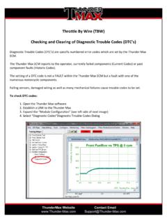
3 If not, download the latest software from the ThunderMax website: 4) Open the ThunderMax software on your shop computer and link to the ThunderMax module on the bike. The Basic Set Up tech video on You Tube is helpful for first time users. The video demonstrates how to link to the module, and can be found here: 5) In the software, go to Map Editing>Read Module Map & Settings, then 6) Map Editing>Read Learned Fuel Adjustments. 7) Under the Tuning Maps tree in the software, select Module Configuration>Diagnostic Codes. 8) On the main tool bar, select TMax Control Center and read additional information about condition of bike's tune as recorded by the ThunderMax . 9) If further assistance is required, select TMax Auto Support on the main tool bar to collect and send your module data to our support team.
4 10) If the condition or complaint has been present since module installation, check and make sure the base map may not be a good match to the engine. Note: If the map has a substantial amount of learned points, it may be beneficial to keep the current map, even if it wasn't originally intended for this setup. Please Note: Your shop computer must have an internet connection to download the ThunderMax software, use the automated support email function, access map updates and watch tech support videos on YouTube. In addition to the steps above, it is a good idea to check the overall condition of the Motorcycle . Be sure to check the following service related items: Fuel System 1) Fuel filter requires service every 25-30k miles.
5 2) Verify fuel pressure, H-D spec is 55-62 lbs - If pressure is low or not holding to spec, remedy this condition before making any adjustments to the map. Ignition 1) How old are the spark plug wires? Inspect wires thoroughly for any rubbed spots that may be suspect. 2) Wires should be replaced every 3 years regardless of mileage. We only recommend the factory OE plug and plug wire. 3) Perform a compression test. Useful Definitions 1. Fuel Pump Located in the gas tank, this assembly pressurizes fuel being sent to the Throttle Body. 2. Fuel Pressure Regulator Pressurized fuel from the pump is sent through this devise where it is regulated at a certain, constant pressure (H-D spec is 55-62 PSI) to the fuel injectors.
6 Consistent fuel pressure is required for a properly running engine. Excess, non-regulated fuel is returned to the gas tank. Located in the gas tank on 2001-up Softails , 2002-up all models (on 1995-2001 Touring models, the regulator is mounted externally, on the throttle body). The second fuel line on 1995-2001. Touring models is the return line for excess fuel since the regulator is mounted externally. 3. Fuel Rail Essentially the manifold for fuel delivery to the fuel injectors. Mounted to the intake manifold of the throttle body, the pressurized fuel line and one side of the fuel injectors are attached to it. 4. Fuel Injectors Electronic on/off valves for injecting pressurized fuel in short pulses into the engine.
7 Pressurized fuel enters the injector from the fuel rail where a small electronic solenoid opens and closes for a specified time to deliver fuel to the engine, where it is mixed with air being drawn into the intake port. The exact timing and duration of the fuel pulse (pulse width) is controlled by the Motorcycle 's Electronic Control Module (ECM). 5. Throttle Body Air and fuel are fed into the engine through the throttle body and manifold assemblies. Sensors are mounted to the throttle body to provide feedback to the ECM regarding throttle position, manifold pressure and intake air temperature. A small electric motor is attached to control engine idle speed. 6. Throttle Position Sensor (TPS) Electronic sensor mounted to the end of the throttle shaft that transmits throttle blade position (twist-grip position) to the ECM.
8 7. Manifold Air Temperature (MAT) Sensor Relays information to the ECM so it can adjust engine requirements based on intake air temperature. Mounted on the throttle body, behind the throttle blade. 8. Manifold Absolute Pressure (MAP) Sensor - Relays information to the ECM so it can adjust engine requirements based on intake manifold pressure. Mounted on the throttle body, behind the throttle blade. 9. Cylinder Head Temperature Sensor Monitors engine temperature and relays information to the ECM. Used by ECM to alter settings for warm-up, normal operating and over-temperature situations. 10. Idle Air Control (IAC) Motor Small electric motor with a pointed-tip plunger that controls the amount of air the engine receives during idle.
9 Mounted to the throttle body, midway on the Idle Bypass Port. The Idle Bypass Port is a passage that bypasses the throttle blade, which unlike a carburetor, is closed nearly airtight at idle. The plunger moves in or out to increase or reduce air through the port, working in conjunction with fuel delivery as dictated from the ECM. This item and its controller also play a big part in the engine warm-up cycle and how an engine descends and returns to idle. 11. Crankshaft Position Sensor (CPS) Mounted on the engine case in the crankshaft area. Crankshaft is Equipped with teeth that trigger the magnetic sensor and relay the data to the ECM, which calculates RPM based on the information received.
10 Multiple teeth allow for precise fuel delivery and spark timing during engine revolutions. 12. Vehicle Speed Sensor (VSS) Mounted on the transmission, reports vehicle movement and speed to the ECM. 13. Electronic Control Module (ECM) The electronic computer or Brain that processes information received and controls all functions of engine management. The ECM collects data from all engine sensors and controls fuel and spark requirements based on its map programming. 14. Oxygen Sensor Device that is attached to the exhaust pipe, usually 4-6 from the cylinder head. It is used to measure the amount of unburned oxygen in the exhaust stream of an operating engine. Two types of sensors are typically used on Harleys , Narrow-Band (factory) and Wide-Band (aftermarket).