Transcription of Set / Reset Point Pressure Switch EN - Graco
1 InstructionsSet / Reset Point Pressure SwitchSet and Reset Point Pressure Switch used to detect Pressure changes. Not approved for use in European explosive : 24K414 Equivalent: IFM Electronic GMBH PK6220 Maximum Working Pressure : 5800 psi (400 bar, 40 MPa)WarningsThe following warnings are for the setup, use, grounding, main-tenance, and repair of this equipment. The exclamation Point symbol alerts you to a general warning and the hazard sym-bols refer to procedure-specific risks. When these symbols appear in the body of this manual, refer back to these Warn-ings.
2 Product-specific hazard symbols and warnings not cov-ered in this section may appear throughout the body of this manual where Safety InstructionsRead all warnings and instructions in this manual and the instructions included with your operating system or pump. Save these SHOCK HAZARD This equipment must be grounded. Improper grounding, setup, or usage of the system can cause electric shock. Turn off and disconnect power at main Switch before disconnecting any cables and before servicing equipment. Connect only to grounded power source.
3 All electrical wiring must be done by a qualified electrician and comply with all local codes and INJECTION HAZARD High- Pressure fluid from dispense device, hose leaks, or ruptured components will pierce skin. This may look like just a cut, but it is a serious injury that can result in ampu-tation. Get immediate surgical treatment. Do not Point dispense device at anyone or at any part of the body. Do not put your hand over the fluid outlet. Do not stop or deflect leaks with your hand, body, glove, or rag. Follow Pressure Relief Procedure in this manual, when you stop dispensing and before cleaning, checking, or servicing equipment.
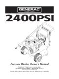
4 Tighten all fluid connections before operating the equipment. Check hoses and couplings daily. Replace worn or damaged parts 23A1827 CPressure Relief ProcedureInstallation1. Disconnect power to Disconnect cable from If replacing a Pressure Switch on an existing installa-tion, relieve Locate unit where shock, vibration and ambient tem-perature fluctuations are minimal. Do not mount in ambient temperature areas exceeding 160 F (71 C). Unit may be mounted in any position. However, if installation location results in frequent expo-sure to liquid it is recommended that the unit be mounted vertically with the Pressure connection down.
5 5. Screw Switch into manifold. Always use a wrench on Pressure connection wrench Test unit before Rotate the top portion of Switch (with the lock and unlock symbols) to align the unlock symbol with the two white arrows (FIG. 1).2. Adjust set Point to the desired Pressure setting. 2500 psi (172 bar, MPa) is the factory default Adjust the Reset Point to the desired Pressure set-ting. 500 psi (35 bar, MPa) is the factory default setting. 4. Rotate the top portion of the Switch to align the lock symbol with the two white arrows (FIG.)
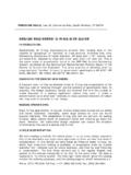
6 2). 5. Recheck set Point and Reset Point and install Switch according to installation LED sRelieve Pressure in the system following the procedure recommended for your operating system or Electrical ratings must not be exceeded. Over-load on a Switch can cause Switch to fail on the first cycle. Never exceed Pressure limits. Unit can be oper-ated up to maximum Pressure on a limited basis ( , set-up, testing) but continuous operation must be restricted to the designated adjustable range. Excessive cycling at maximum Pressure limits could reduce sensor life.
7 FIG. 1 FIG. 2 Steady Green LEDP ower is supplied to Pressure Switch . Yellow LED turns off and onWhen you reach Pressure , yellow LED lights. When Pressure drops below Reset value, yellow LED turns ProblemCauseSolutionIn an injector installation only, pres-sure Switch activates before all injec-tors firePressure Switch is installed at the wrong locationVerify Pressure Switch is correctly installed - downstream from a bank of injectorsPressure Switch is not set to a high enough Reset pointVerify Pressure Switch is set suffi-ciently high at a level above the firing Point of the injectors and within the margin for Pressure Switch or Pressure gauge on the system reads different than the Pressure switchPressure Switch is installed at the wrong locationVerify Pressure Switch is
8 Correctly installed - downstream from a bank of injectorsPressure Switch is not set to a high enough Reset pointVerify Pressure Switch is set suffi-ciently high at a level above the firing Point of the injectors and within the margin for all injectors have Reset , the Pressure Switch does not deactivate The Reset Point is set too lowTurn the Reset Point to a higher set-ting. Then verify the system is func-tioning Pressure Switch seems to be operating backwardsNormally Open and Normally Closed outputs not completing connectionCheck the Normally Open and Nor-mally Closed outputs and make sure the proper connection is made.
9 Adjust connection as is supplied to the Pressure Switch but the Switch is no longer sensing pressureGrease soap has accumulated in the sensing orifice. 1. Attempt to lower the Pressure Switch set Point to verify the Switch is not sensing any After verifing the Pressure Switch is not sensing Pressure , remove the Switch from the port. 3. Using a non-metalic tool, clean out the sensing orifice. 4. Reinstall the Switch in the written and visual data contained in this document reflects the latest product information available at the time of publication.
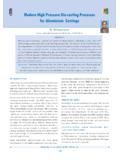
10 Graco reserves the right to make changes at any time without Instructions. This manual contains English. MM 3A1827 Graco Headquarters: MinneapolisInternational Offices: Belgium, China, Japan, KoreaGRACO INC. BOX 1441 MINNEAPOLIS, MN 55440-1441 Copyright 2011, Graco Inc. is registered to ISO DataDimensionsWiring DiagramGraco Information TO PLACE AN ORDER, contact your Graco distributor or call to identify the nearest : 612-623-6928 or Toll Free: 1-800-533-9655, Fax: 612-378-3590 Electrical DesignDC PNPO utputNormally open /closed complimentaryOperating - 32 VDCA mbient Temperature Range-13 to 176 F (-25 to 80 C)Storage Temperature -40 to 212 F (-40 to 100 C)Current Rating500 mAVoltage Drop< VCurrent Consumption<25 mASet Point Range290 - 5800 psi (20 - 400 bar.)