Transcription of SFD DRYER APPLICATIONS - SKF.com
1 SFD Air DRYER Owner s Manual 10/09/2014 Table of Contents SAFETY MESSAGES IN MANUAL AND IN WARNING LABELS .. 3 SEPARATOR FILTER DRYER .. 4 SPECIFICATIONS SFD DRYER SYSTEMS .. 5 SFD DRYER SIZING CHART .. 6 GENERAL MOUNTING INSTRUCTIONS: .. 7 BASIC OPERATION AND INSTALLATION MOUNTING INSTRUCTIONS .. 8 Micro Logic Timer .. 8 Programmable Logic Control (PLC) 120 thru 800 .. 10 Pneumatically Controlled (PC) 40 thru 200 CFM SFD DRYER Systems .. 11 ANNUAL INSPECTIONS .. 12 MLT (Micro Logic Timer) Dryers .. 12 PLC (Programmable Logic Control) Dryers .. 12 PC (Pneumatic Control) Dryers .. 12 FLOW DIAGRAMS .. 13 SERVICE COMPONENTS .. 17 Micro Logic Timer (MLT) APPLICATIONS (5 120 CFM DRYER Systems) .. 17 Programmable Logic Control (PLC) APPLICATIONS (120, 240 400, 600, 800 CFM DRYER Systems) .. 19 Pneumatically Controlled APPLICATIONS .. 21 TROUBLESHOOTING SFD AIR DRYER SYSTEMS .. 23 MLT, PLC and Pneumatically Controlled Operation/Cycle & Problem 23 SERVICE REPLACEMENT PROCEDURES SFD AIR DRYING SYSTEM.
2 27 desiccant Cartridge Kit Options .. 27 Adapter Plate/Cartridge Stud .. 27 Micro Logic Timer Replacement (MLT) .. 29 Air Control Valve - MLT DRYER Systems .. 29 Inlet Check Valves .. 30 Outlet Check Valve .. 31 Regeneration Valve .. 31 Heater Assembly .. 32 Reset pneumatic control .. 32 OIL COALESCER .. 33 Installation and How It Works .. 33 Float Drain Service Procedures .. 35 ILLUSTRATIONS .. 35 Service Components .. 36 Air DRYER Systems .. 40 ACCESSORIES .. 48 Moisture Minder .. 48 Regeneration Flow Cut-Off Kit .. 49 Installation .. 49 Troubleshooting Regeneration Cutoff Solenoid (RCS) .. 49 PART NUMBERS .. 51 Service Components .. 51 Air DRYER Systems .. 52 GLOSSARY OF TERMS .. 52 WARRANTY .. 60 WARNING Read, understand and follow safety precautions and instructions in this manual and in the labels attached to the DRYER system. Failure to do so could result in serious injury, death and property damage. 2 SAFETY MESSAGES IN MANUAL AND IN WARNING LABELS Safety messages appearing in the manual and on warning labels utilize signal words that translate to a level of risk.
3 Below are the definitions of the words used: WARNING: Indicates a hazardous situation that, if not avoided, could result in death or serious injury. CAUTION: Indicates a hazardous situation that, if not avoided, could result in minor or moderate injury. REMINDER: Indicates suggestions for proper use. Warning labels are attached to the air DRYER . They look something like those below. Be sure that these labels are visible and in place. If they become damaged or illegible, contact SKF for replacement labels -WARNING- BEFORE SERVICING SFD DRYER UNIT(S) RELIEVE ALL AIR PRESSURE FROM DRYER UNIT(S) AND AIR LINES DO NOT OVER-TIGHTEN CARTRIDGE Lubricate threads, O-rings & flat gasket with grease provided before installing cartridge Tighten cartridge turn only after gasket contacts casting surface 3 SEPARATOR FILTER DRYER (SFD) Protect compressed air lines from oil, water and particulate The easy to maintain SFD is a compact heatless desiccant air DRYER which delivers high quality compressed air capable of achieving superior pressure dew points -40 F or lower.
4 Use the SFD when precision work requires high quality air. Reduce energy and operating costs with the SFD. Contaminated compressed air lines drags down productivity, raises operating costs, and increases maintenance requirements. SFD benefits include: Requires less electrical usage than alternatives Extends service life of pneumatic driven devices Avoid expensive downtime to repair or replace equipment Reduces prep time in spray APPLICATIONS Eliminates rework due to compressed air contaminants Modular design allows for quick, easy and flexible expansion Simple and easy to service: Maintenance personnel can easily spin off the desiccant cartridges and replace service components in a matter of minutes. Designed for outdoors - complies with NEMA 4 Standard - when equipped with thermostatically controlled heater package keeps DRYER performing during winter months. 1a Inlet Port ( ") wet air to DRYER 3a Wet air enters desiccant bed 4b Wet air removed fro m desiccant bed 3b Dried air desorbs (removes)
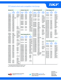
5 Condensate fro m bed 2a After passing through micron filter pad, wet air enters cartridge 2b Dried air enters desiccant bed via regeneration valve 4a Wet air adsorbed onto desiccant bed 1b Wet air removed fro m DRYER Cartridge A @ system pressure Cartridge B @ atmospheric pressure desiccant Cartridge A desiccant Cartridge B Listed are types of operations that significantly reduced operating costs Paint/foam spraying Sand/shot blasting Air tools Vehicle wash stations Packing equipment Lab measurement equipment Drilling equipment Railcar braking systems & Loci s Mining car dump stations Dust collection systems Baghouse equipment Bottling equipment Plasma cutting Drag line shovels Batch mixing Rail maintenance equipment 4 SPECIFICATIONS SFD DRYER SYSTEMS Micro Logic TimersProg rammable Log ic ControllerPneumatically ControlledElectrical Requirements (M LT )(PLC)(PC) Clas s 1 d iv 2110 v o lt .072 amp ere NEMA 4110 v o lt.
6 090 amp ere NEMA 4 Meets NEMA 7 Requirements 24 v o lt amp ere NEMA 4 12 v o lt amp ere NEMA 4 110 v o lt, 75 watts , .68 amp ere each110 v o lt, 75 watts , (.68 amp ere) each24 Vo lt, 75 watts , amp ere each24 Vo lt, 75 watts , ( amp ere) each12 Vo lt, 75 watts , amp ere each12 Vo lt, 75 watts , ( amp ere) each " NPT <40 cfm " NPT <80 cfm*1 " NPT manifolds1 " NPT* 619780 kit fo r 80 cfm d ry er s y s tems optional90 - 190 PSI90 -190 PSI90 - 190 PSI2 cartridge system 40 lbs2 cartridge system 50 lbs4 cartrid g e s y s tem 120 lb s2 cartridge system 50 lbs4 cartrid g e s y s tem 100 lb s6 cartrid g e s y s tem 170 lb s4 cartrid ge s y s tem 120 lb s8 cartrid g e s y s tem 240 lb s6 cartrid g e s y s tem 170 lb s12 cartrid g e s y s tem 340 lb s18 cartrid g e s y s tem 510 lb s24 cartrid g e s y s tem 680 lb s2 desiccant w/ 4 pound cartridges H= " L= " W = "4 desiccant w/ 4 pound cartridgesH= " L= " W = "6 desiccant w/ 4 pound cartridgesH= " L= " W = "8 desiccant w/ 4 pound cartridgesH= " L= " W = " - 2 rows12 desiccant w/ 4 pound cartridgesH= " L= " W = " - 2 rows18 desiccant w/ 4 pound cartridgesH= " L= " W = " - 3 rows24 desiccant w/ 4 pound cartridgesH= " L= " W = " - 4 rows<80 cfm 75 lb s<240
7 Cfm -175 lb s<400 cfm - 251 lb s<480 cfm - 350lb s<800 cfm - 502 lb s<1200 cfm - 753 lb s<1600 cfm - 1004 lb s2 desiccant w/ 8 pound cartridgesH= " L= " W = "4 desiccant w/ 8 pound cartridgesH= " L= " W = "6 desiccant w/ 8 pound cartridgesH= " L= " W = "12 desiccant w/ 8 pound cartridgesH= " L= " W = " - 2 rows18 desiccant w/ 8 pound cartridgesH= " L= " W = " - 3 rows24 desiccant w/ 8 pound cartridgesH= " L= " W = " - 4 rowsYe sYe sYe s--Inlet/Outlet PortsWeight desiccant CartridgesHeatersNA1 " NPTO perating Pressures (All DRYER Systems)Dimens ionsModular (expandable)Dimens ions Weight w/ 8 Pound desiccant CartridgesContact SKF Customer Service @ (888) 753 3477(include external SKF oil coalescer)(include external SKF oil coalescing prefilter)5 SFD DRYER SIZING CHART Max CFM Flow HPMLT Pa rt#Filtration (micron)TypeVoltageBracket# of rows# of Dr ye r s ( 2 ca rt. Ea )Max Length (L)Weight (lbs.)
8 * * * Heater equipped6 Read and understand entire instruction manual before installing or servicing of SFD SFD DRYER systems not designed for use other that removal of water from compressed air SFD DRYER systems cannot be used for breathable air Never connect or disconnect a pipe/line containing air pressure or remove a component, fitting or pipe plug unless you are certain all air pressure has been shut off and relieved Always wear proper eye protection and never look directly into ports of SFD Sound decibels without silencer @ 120 db / with silencer @ 37db Never exceed recommended working air pressure of 190 bar A by-pass system recommended making servicing of SFD DRYER units easier and safer Use only proper tools and observe all precautions pertaining to the use of those tools GENERAL MOUNTING INSTRUCTIONS: Allow 2 min above cartridges for cartridge removal Air line routing and connections may be modified to accommodate space and application All air line connections require thread sealant Aluminum threads require an anti-seize compound (included within SFD DRYER service kits)
9 Optional thermostatically - controlled heaters available for MLT and PLC DRYER systems SFD DRYER systems must be mounted with the exhaust ports positioned downward and desiccant cartridges in upright position Mount SFD utilizing 3/8 grade 5 bolts, washers, lock washers and nuts are recommended and not furnished with air DRYER kits Manifold design may be either square or round Plug electrical connection to dedicated and accessible wall receptacle Electrical cord replacement only with timer and coil only cord and plug not serviced separately WARNING Read, understand and follow safety precautions and instructions in this manual and in the labels attached to the DRYER system. Failure to do so could result in serious injury, death and property damage. 7 BASIC OPERATION AND INSTALLATION MOUNTING INSTRUCTIONS Micro Logic Timer (MLT) manages regeneration cycles by energizing and de-energizing the air control valve at two-minute intervals.
10 However, when the air DRYER is initially powered on, the MLT begins a startup sequence of four ten-second cycle intervals, and when completed, MLT begins cycling every two minutes. An LED on the MLT will be "on" during energized (charge) cycle and "off" during de-energized (regeneration) cycle. When LED is on, the left desiccant cartridge receives wet air and the right desiccant cartridge regenerates. After two minutes MLT ( DRYER ) switches, LED is off as left canister now begins regeneration process and right desiccant cartridge receives wet air. A light flow of air from the desiccant cartridge through DRYER s exhaust port is normal during regeneration cycle. There should be no venting of air from desiccant cartridge when receiving wet air. When an SFD cycles, there will be a momentary burst of air from one SFD exhaust port (muffler). This is normal and will occur each time DRYER cycles. Four cartridge MLT systems will have two cartridges regenerating one from each DRYER unit, , cartridges 1, 3 charge cycle, cartridges 2, 4 regeneration cycle 1.