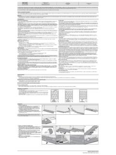
Transcription of SIDE-HINGED DOOR UNIT Step 1: Prepare Rough Opening …
1 Step 1: Prepare Rough Opening Step 3: Prepare Door Unit Step 4: Place Door in Rough Opening SIDE-HINGED Door Types Information Panel SIDE-HINGED DOOR UNIT. installation INSTRUCTIONS Remove all packaging materials such as nails, staples and screws. Instructions vary according to door type. Confirm which door type is How to Plumb the Door Some dwelling designs/conditions may require special installation steps, consult your being installed. some door styles not available in all markets. For all door types, it is essential that the frame is in a straight architect, design professional and/or product manufacturer for additional guidance. 3 vertical plane and is not twisted. Check alignment using this For single door unit, use Step 5A. For double door unit, use Step 5B. method: Stand on the outside of the door. Check that the Required Tools & Materials For single door unit with one or two sidelites, use Step 5C.
2 weatherstripping on the latch side is evenly compressed along the entire height of the door slab without any pinching or gaps (Figures 9 and 10). Figure 1: A clean, level, solid sub-floor area is essential to successful installation. A: DO NOT utilize the wall to square and level unit. Unit must be square and level to insure proper operation and performance. Ensure that the following conditions are met: Clean, clear work area The Rough Opening (RO) is ideally 1 wider and 1/2 taller single door than the outside frame dimensions of the door unit. Units Figure 3: Some door units will be supplied with plastic covers over the bottoms (X for operable panel or O for non-operable panel). intended for installation in high velocity windstorm markets of the jambs. These must be removed before installation. require less clearance between unit and RO (1/4 sides & top). The RO is plumb, square and level The old door frame has been completely removed in retro-fit installation B: The sub-floor area is clean, dry and level Figure 6: Place the sill in the Opening first and then tilt the door up into the Opening .
3 The existing sub-floor area is at least 6 deep for 4-9/16 . frames and at least 8 deep for 6-9/16 frames. Door units featuring multiple door panels or glass inserts are Because a solid, level sub-floor is absolutely essential for proper heavier and more difficult to handle - do not attempt to handle without assistance. double door door unit installation, do not proceed with the installation until (XX for unit featuring two operable panels). the sub-floor is both solid and level. Figures 9 and 10: The weatherstripping on these doors is not evenly Step 2: Caulk the Sub-Floor compressed. How to Fasten the Door C: After shimming, the door is fastened to the studs by installing screws through the jambs, shims and into the stud (Figure 11). Screws located in hinge or strike position shall be placed in the Figure 4: Some door units may be supplied with a wood or cardboard skid plate thin (rabbet) section of frame, other screws shall be placed in located along the bottom of the door.
4 Needs to be removed. thick (stop) section of frame. Wide frames should be attached Critical Point: Although all steps are critical, this symbol single with two sidelites with a screw in both sections of the frame to minimize rotation. identifies procedures requiring extra attention. (OXO for unit featuring operable panel with two non-operable panels). Figures 7 and 8: The exterior trim (brickmould) rests up against exterior sheathing or slides into the Opening of exterior brick. When shims are properly installed, the frame should not move Check Your Work: This symbol identifies when the work should 3 or twist when the screws are tightened and counter-sunk, thus 3 be checked for correctness before continuing with installation. Figure 2: Caulk is applied in three parallel lines running the width of the sill. Stand on the outside of the doorway. With the exterior side of maintaining the gap between the edge of door panel and 1.
5 8. Variations in threshold design may require that the caulk lines be the door unit facing you, tilt the door unit toward you (Figure 6). The frame. If there is any movement, loosen the screws and shim tighter to maintain the gap, then retighten the screws. 1. PLEASE NOTE: Failure to install this unit in accordance with applied directly to the bottom of the door unit to ensure a brickmould (not supplied with all units) should rest up against the 8. architect, design professional or product manufacturers instructions will necessary weather-seal. Inspect the bottom of door unit to Remove this por- siding of the exterior wall (Figure 7) and should slide into the RO of a have a direct effect on the units performance and/or long term wear. confirm it features a flat surface before caulking the sub-floor tion of plug prior brick home (Figure 8). Installer shall be experienced in performing work required and shall be area.
6 To installing. specialized in installation work similar to that required for this project. If door unit is supplied without a clip or plug holding door single or double door with one sidelite Figure 5: Some door units may be supplied with a clip or plug holding the Warranty claims are subject to site inspections by a qualified Apply three 1/4 lines of caulk along the length of the sub-floor, the first panel aligned and closed during the initial installation steps. Do not remove at aligned and closed, do not leave the door wide open during (OX or XO for unit featuring operable panel with non-operable panel) Figure 11: Screws are installed manufacturer's representation to establish probable cause and proposed line starting approximately 1 from the inside edge. The lines should be through the jamb, shims and into the this time. Some door units may be supplied with a double headed nail or screw installation.
7 The weight of the door may cause it to fall and 2x wood studs or bucking. corrective action. about 1 apart. holding panel closed - this needs to be removed at this time. cause injury. Step 5: Shim and Fasten Step 5: Shim and Fasten Step 5: Shim and Fasten Step 5: Shim and Fasten Step 5: Shim and Fasten Step 5: Shim and Fasten Step 5A: For single doors Step 5B: For double doors with concealed top and bottom flush bolts Step 5C: For door with sidelites X Ensure that there is an even gap across the top of the door slab. XX threshold and weatherstrip block around the foot bolt, the hole is not XO For units with only one non-operable panel attached on the latch side deep enough (the weatherstrip block must touch the threshold to of the door: The second set of supplied screws are installed through properly seal the unit). Shim tightly behind the vacant hinge screw hole the thin (rabbet) section of the jamb using the vacant hinge screw holes B C Note: Units With the door closed and from the inside shim directly behind the B B Note: Units in the bottom hinge (Point C in Figure 16) until the lower flush bolt B C Note: Units vacant hinge screw hole in each hinge (Points D and E in Figure 12) (Figure 21).
8 Typically long security screws are used to install the dead intended for intended for slides freely into the clearance hole in the sill. Secure the door by intended for F D installation in until there is a consistent gap between the hinge-side jamb and the 1. 8 E C installation in driving a 2 installation screw supplied, through the hinge and jamb 1 installation in bolt strike plate (Step 6). E D. 2. high veloc- door slab edge along the entire height of the door. Gap between the high veloc- and into the stud. If the flush bolt does not slide freely, loosen the high veloc- ity windstorm ity windstorm ity windstorm For units with only one non-operable panel attached on the hinge side latch-side jamb and the door slab edge should be at the top and screw, shim more tightly and then tighten the screw. 1. of the door: The second set of supplied 2 screws are installed through 1.
9 G regions may 8. bottom of the door only. Drive one of the 2 screws supplied through 1. regions may F regions may 2. F the thin (rabbet) section of the jamb under the weatherstripping through G E require additional 2. the vacant hole in each hinge, through the jamb, shims and into the F F require Shim behind the vacant hinge screw hole in the top hinge (Point D D require the shim and into the stud approximately 8 from the top and bottom of points of additional points in Figure 16) to align the top flush bolt with the clearance hole in the additional points attachment. See stud or Rough buck (Figure 11). of attachment. header (Figure 17). Secure with the 2 installation screw supplied, 1 of attachment. the jamb (Figure 22). Shim just above and below the dead bolt hole and 2. local retailer for See local retailer See local retailer drive the supplied 2 installation screws through the dead bolt strike 1.
10 Through the hinge jamb and into the stud. installation sheet When the shims are for installation E D for installation plate (Step 6). 2. F E supplement. 3 properly installed, the E D sheet supplement. From the outside and with the door closed, ensure that the frame sheet supplement. frame should not move or 3 is in a straight vertical plane (not twisted). To do this check that 3 When shims are properly installed, the frame should not move or twist at all when the screws the weatherstripping on the astragal side is evenly compressed twist at all when the screws are tightened and counter-sunk, thus along the entire height of the door slab without any pinching or maintaining the gap. If there is any movement, loosen the screws 1. A A are tightened and A A A A 8. counter-sunk thereby gaps (see Figures 8 and 9). and shim tighter to maintain the gap, then re-tighten screws.