Transcription of Silicon Controlled Rectifiers and Transformers in Power ...
1 Silicon Controlled Rectifiers and Transformers in Power control How Transformers extend the capabilities of SCRs Arthur Holland, Holland Technical Skills The most common and economical arrangement of SCR Power control is an SCR unit inserted between the ac Power line and a constant resistance load that has a voltage rating that matches an available standard Power source. Sources with more than about 10kW capacity are usually in the 400 600V range. Heaters suitable for industrial processes are rugged and often demand lower voltages.
2 Here are some cases where you need a transformer between the Power source and the load. 1. The load has low resistance and needs a low voltage and high current. A typical example would be where you have to provide a few volts at some hundreds of amps to heat directly a length of steel pipe and the fluid inside it. 2. Other loads needing special treatment include Silicon carbide, molybdenum, tungsten, molybdenum disilicide and graphite. These may demand a low and adjustable voltage ac Power source. After you have specified the transformer you have to decide where to connect the SCR.
3 SCR in the Secondary is usually problem free, but you will usually need a higher current, lower voltage rated SCR. This could be more expensive and call for extra heat sink dissipation. Given reasonably constant load resistance you can use the lower cost fast-cycling mode or even use solid-state-contactor (SSC) - cheaper yet because your controller generates the control pulses. 1or Power limiting. These are only found with pbide heaters a tapped transformer is ed t where phase-angle ed ig 1 SCR and Transformer ansformer option lets you run with a higher Power factor.
4 Or you are hit with a maximum demand low voltage high current secondary suits multiple Silicon carbide elements in parallel. This If your heaters have temperature or age-dependent resistance this calls for features like current, voltage hase-angle control . With Silicon car often used, combined with some phase-angle controllvoltage limiting. The taps are often fitted in the primary, especially where the secondary current greatly exceeds that in the primary. You can now move the available secondary voltage progressively higher as the elementresistance increases with age.
5 Compared with the arrangemenadjustment performs all the voltage limiting, the tapp F trWhat if your energy bill is based on kVAHr rather than KWHrmonthly charge? You should select the transformer tap that lets you operate at a near sinusoidal current waveform. Even change the tap setting for different load conditions; at start-up then at steady state when up to working temperature. Aarrangement balances their aging by reducing the Power taken by early-aging elements as theirresistance increases. SCR in the Primary dictates that your SCR is rated for line voltage and usually a lower current.
6 This can save cost and minimize SCR heat sink dissipation in your control enclosure. The firing must be phase-angle with soft start and here are the reasons: With fast-cycling you risk a current inrush at switch-on and at every ON cycle. This can be up to 8 times full load current. The initial primary current aims to reach V/R a very high value because R is the very low primary winding resistance. What limits primary current? Mostly Back emf. This acts in opposition to the line voltage. It appears when the onset of primary current causes a flux change in the transformer core.
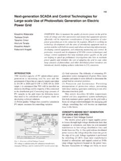
7 If you are lucky, the flux will undergo a large change when the SCR switches on. The result in this case is a large dose of back emf that limits the current inrush. But what if the last current turn-off left the remanent flux positive as shown in Fig 2? And let s say the next switch-on causes the current to push the flux also positive. This leaves little headroom for the flux to increase much before magnetic saturation of the core. Here the dose of back emf is too feeble to prevent a large current inrush and the fuse pops. The polarity of the remanent flux in relation to that of the next pulse of primary current is unpredictable.
8 So as a general rule do not use fast cycling control when you have the SCR in the primary. Use phase angle control with soft start. Fig. the result of a step application of control signal when you use phase-angle firing and soft start. The SCR ramps the Power up to the new value over several cycles. The transformer flux performs a succession of growing hysteresis loops like that in Fig. 2 and the Controlled build up of back emf holds off any abnormal current inrush. Fig 2 Transformer Core Flux The load on the secondary may have a low cold resistance or may be abnormally low anyway.
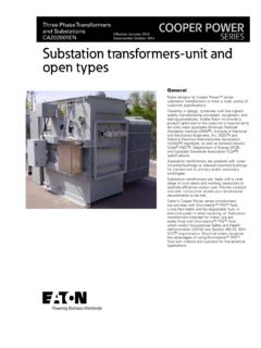
9 In this case you will need the current limiting feature. Soft start will give the current limit circuit the short time that it needs to get to work. Fig 3. Soft Start 2 Three Phase Systems All the considerations of single-phase systems noted in Part 1 last month apply equally to 3-Phase systems. Of the various primary/secondary combinations of wye and delta the delta/4-wire wye shown in Fig 1. has become the most frequently used. The reasons? The delta primary provides the best primary current balancing for a given secondary unbalance.
10 Third harmonics readily circulate round the delta, thereby reducing harmonic distortion of the supply. The wye secondary offers you two choices of secondary voltage 480V line to line and 277V line to neutral. Grounding of the secondary neutral conductor gives the least voltage-to-ground. This is a safety issue. You can run fast-cycling loads and even the most difficult phase-angle loads. Transformer voltage and current relationships under sinusoidal conditions. Say the transformer in has a 1:1 voltage ratio in respect of line-to-line voltage 480/480V.