Transcription of Simplified Tools and Methods - K8IQY
1 Simplified Tools and Methods for Measuring CrystalsByJim Kortge, K8 IQYS ummaryThis paper describes an approach for measuring crystal parameters using relatively simple testapparatus and test setups. Some of the required test instruments are easily built, usingManhattan-style construction Methods . Others can be obtained on the surplus market at low careful use, the resulting crystal parameter values are comparable in accuracy to thosemeasured with instruments costing thousands of dollars. The same instruments and setup canalso be used for measuring crystals for use in multi-pole of the common elements in all modern superheterodyne receivers is at least one crystal contest grade receiver may employ more than one filter for improved performance. One canobtain a crystal filter essentially two ways; either purchase a commercial unit on the required IFfrequency or build the filter from easily obtained the filter requires little effort, but the cost is high, on the order of $ , and maybe much more than this amount for a high performance filter.
2 On the other hand, the componentsto build a filter will probably cost one-tenth of the commercial unit, but effort is required to buildthe filter. Most of that effort is embodied in determining the characteristics of the crystals thatwill be used. The remainder is in assembling and testing the constructed are the benefits of building a filter? First, one can tailor the filter s characteristics toexactly those desired. For example, the filter could be built for CW use with a pass band of 350Hz. Obtaining a commercial filter with that bandwidth is prohibitively expensive, since it is nota standard. Another reason for building our own filter is the ability to choose the number ofelements needed to achieve the performance desired. If a 4-pole filter is needed, that s what isbuilt. On the other hand, if a 7-pole filter is desired for enhanced performance, it too can be builtwith little additional effort.
3 We can even build a filter with an adjustable pass band; try to findone of those commercially. Finally, by building our own filters, we have many more optionsavailable in deciding the RF mixing schemes used. With commercial filters, most of thosedecisions are dictated by the offerings of the various manufacturers, which are limited unless acustom filters is ordered. Crystal ParametersBefore we can build a crystal filter, we have to know the properties of the crystals that will gointo it. If the filter is built without that knowledge, two important deficiencies will occur. First,the filter will probably be far from optimum in performance. There will most likely be artifactsin the pass band amplitude and phase characteristics, and the insertion loss will not beminimized. Second, our ability to reproduce the filter, regardless of its performance, or lack of,will be compromised.
4 A second unit built from the same kind of parts will most likely bemarkedly different in performance. Notice that I used the term most likely since by chance,one may end up with a good filter, with reproducible characteristics, without knowing anythingabout the crystal elements used. However, the probability of that actually happening is very, verysmall. The remainder of this paper will concentrate on the equipment and test setups required toascertain this vital informationCrystals are characterized by the following parameters:Fs = this is the series resonant frequency of the crystal, and represents the point where theseries inductive and capacitive reactance terms = this term is the equivalent series resistance of the crystal at resonance (Fs), andrepresents the energy loss in the quartz = this term is the motional inductance of the crystal, and represents the vibratingmass of the quartz = this term is the motional capacitance of the crystal, and represents the elasticity ofthe quartz elementCo = this term is the holder capacitance of the crystal, and is the capacitance of the platedcontact areas on the quartz element, the connecting lead wires, and the parasiticcapacitance to the surrounding = this term represents the overall energy loss in the crystal when it is being driven byan external source.
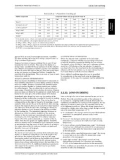
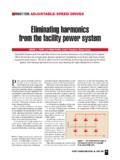
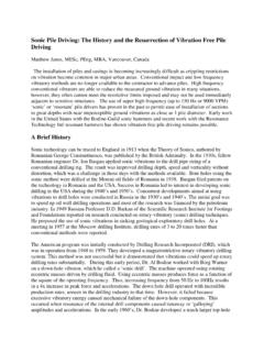
5 It is equivalent to the Q of a capacitor or 1 shows a typical electrical schematic for a crystal, with the various parameters can be seen, the basic structure is a series RLC circuit comprised of Rs, Lm, and Cm, with Coin parallel with the RLC elements. This might suggest that the crystal will behave differentlydepending on the frequency exciting it, and that s exactly what happens. Figure 2 is a frequencyresponse, or Bode plot for a MHz crystal, typical of the crystal element used in the2N2/40+ IF filter, or the IF filter in a K1 or suggested, we see a very sharp response peak from the series RLC part of the circuit atnominally the frequency marked on the case. However, there is also a very deep null about 10 KHz higher in frequency, at the parallel resonance point. This is where the series motionalcapacitance is absorbed into the motional inductance, and the parallel holder capacitance term,Co now prevails.
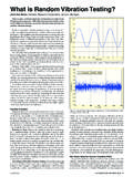
6 Notice that the difference in amplitude between the series resonant peak andthe parallel resonant null is about 100 dB. This very large dynamic range makes it difficult to seeor measure the parallel resonance of a crystal unless one has access to an instrument with acorresponding very wide dynamic range. A spectrum analyzer, or similar instrument is typicallyrequired to make this are the parameters for this crystal:Fs = MHzRs = OhmsLm = HenryCm = FaradCo = FaradQ = 167,500 Crystal Parameter Measurements - OverviewFigure 3 is a block diagram of the basic setup used to measure the crystal parameters. This arrangement employs a signal generator with good short-term stability and precision, acounter to measure the signal generator frequency if the generator does not have its own readout,a fixture to hold the crystal under test, and a suitable RF details on each of the blocks in this diagram are appropriate.
7 The signal generator can varywidely in terms of its capability. It can be a highly accurate, digitally synthesized, low phasenoise, mega-dollar unit from Agilent or Rhode & Schwartz. It could be a lower cost, older unitfrom Racal, Fluke, or HP, such as an 8640B. Or it could be a very low cost, rather simple buthighly stable, VXO based generator, built Manhattan-style that utilizes one of the crystals thatwill eventually be incorporated into a filter. We ll see details of this generator type later counter may or may not be needed, depending on the design of the generator. Which-everway it is implemented, it must be capable of resolving 1 Hz at the crystal s resonant frequency,and have both good short term and long term stability. Almost any crystal base counter willsuffice if the resolution requirement is met. The Arizona QRP Club s Stinger Singer would be suitable as a low cost special crystal test fixture is required as part of this system.
8 It must mechanically hold thecrystal, and more importantly, provide appropriately conditioned signals to the crystal under test,and to the downstream detector. This element is also rather simple in design, and can beconstructed Manhattan-style, using readily available parts. We ll see details of this test fixturelater on final element in the system is some kind of RF detector. This could be something as simpleas an RF probe, used with a digital voltmeter, or analog VOM. It could also take the form of alow bandwidth oscilloscope, with or without the RF probe used as a demodulator. My favorite isa HP 400EL AC voltmeter. These are available on the used equipment market, typically forunder $50, and provide detection and an analog display in dB up to 10 MHz. A suitablealternative is a used HP 3400A. It has the same basic capabilities as the 400EL, but its primaryscale is those crystal parameters shown earlier, only Fs, Rs, and Co are directly measured.
9 Theremaining are obtained by way of additional measurements, and a set of equations to computethem. Here are those equations:Lm = (25+Rs)/(2*PI*DeltaF) where DeltaF is the frequency difference between the 3 dBpoints on the response curveCm = 1/(4*PI^2*Fs^2*Lm) Q = (2*PI*Fs*Lm)/RsThe actual crystal characterization is done a piece at a time, with the next parameter beingderived from previous information in most cases. After we look at the details of the signalgenerator and crystal test fixture, we ll come back to these equations and see in detail how theyare Generator Details A Precision VXOAs was suggested earlier, one of the options for generating a stable signal for crystal testing is touse a VXO. The one that I am presenting fills the need for a precision, stable source, capable ofproviding measurement results comparable to those obtained with a high end, commercial signalgenerator.
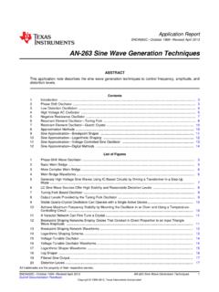
10 Over the past several years, I have suggested this approach to several experimenters,but am not aware that any actually tried it. I wasn t sure the idea was sound until a prototype wasbuilt, and several sets of crystals had been tested. The results using this generator werecomparable to those obtained using my Racal-Dana schematic for this Precision VXO design is shown in figure generator consists of a Colpitts oscillator, Q1 using a 2N5484 junction FET. The crystalemployed is one from the set, which will be used for building a filter or for LO the frequency of oscillation is accomplished with a varicap diode, a MV209, and aset of 5 molded inductors configured as a binary weighted set. Inductance needed to force thecrystal to oscillate at its marked case frequency is experimentally determined by selecting thedesired total inductance using switches S1 through S5.